Red Dot Sight Core Technologies
Core Technologies Behind Our Red Dot Sights
A mature red dot sight is not created by simply assembling an LED, a circuit board, a reflective lens, and a CNC-machined housing.
At FORESEEN OPTICS, development begins with the illumination system, followed by optical matching, precision mechanical design, and mass-production planning. Every technical decision made at an earlier stage directly defines the design boundaries of the next stage.
Our core capability lies in systematically controlling the entire red dot sight development chain—from the light source and optical system to the mechanical structure and reliable mass production.
Overview of Four Core Technologies
| Core Technology | Primary Challenges Addressed | Key Technical Elements | Final Product Performance |
| Graded Illumination and Low-Current Power Management | Whether the aiming dot remains crisp, stable, and energy-efficient | LED spectrum selection, LED binning, emitter aperture design, brightness control, and low-power circuitry | Crisp dot definition, stable brightness, and reliable battery life |
| Optical Matching and Coating Design | Whether the viewing window remains clear and parallax is effectively controlled | Reflective lens materials, cemented or aspheric lens processes, spectral coatings, and protective window parallelism | Low color distortion, minimal ghosting, and reduced parallax |
| Precision Adjustment and Structural Durability | Whether the sight can be adjusted accurately and maintain zero | Adjustment screws, preload mechanisms, CNC tolerances, component retention, and environmental sealing | Reliable adjustment, recoil resistance, waterproofing, and fog resistance |
| Rapid Productization and Low-MOQ Delivery | Whether a design can be converted into a stable, manufacturable product quickly | BOM planning, assembly sequencing, inspection checkpoints, material inventory, and flexible production | Rapid prototyping, low-MOQ production, and consistent delivery |
1. Low-Power Stable Emission Control
Core Definition
The development of a red dot sight begins with its illumination system.
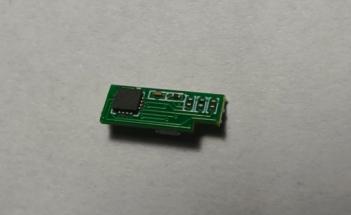
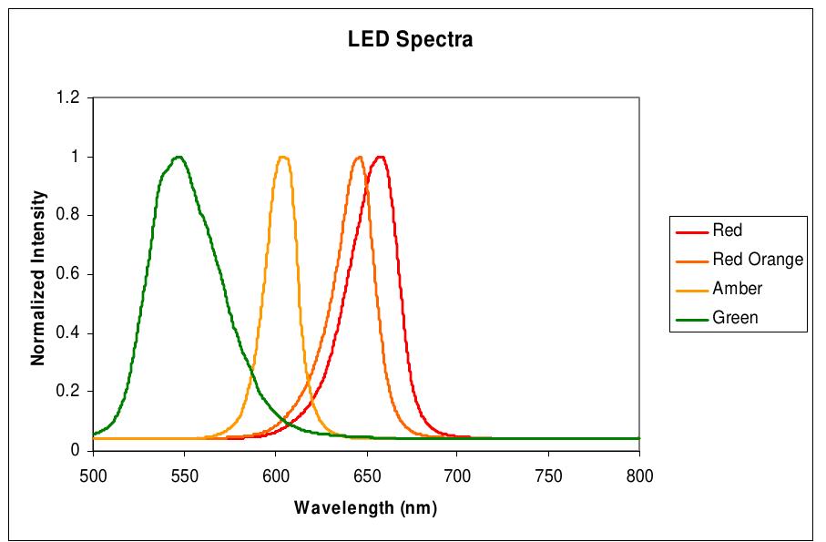
Based on the target market, firearm platform, ambient lighting conditions, and reticle requirements, we define the LED spectrum, emitter size, drive current, brightness range, and power-management strategy. These decisions then serve as the foundation for the subsequent design of the reflective lens and optical coatings.
Core Technologies
- Red, green, and gold LED spectrum selection
- LED binning for brightness, color tone, and power consumption
- Matching the emitter chip to the target dot MOA size
- Control of emitter aperture size, shape, and edge sharpness
- Design of dot, circle-dot, and multi-reticle configurations
- Brightness grading for daylight, ultra-bright, and night vision modes
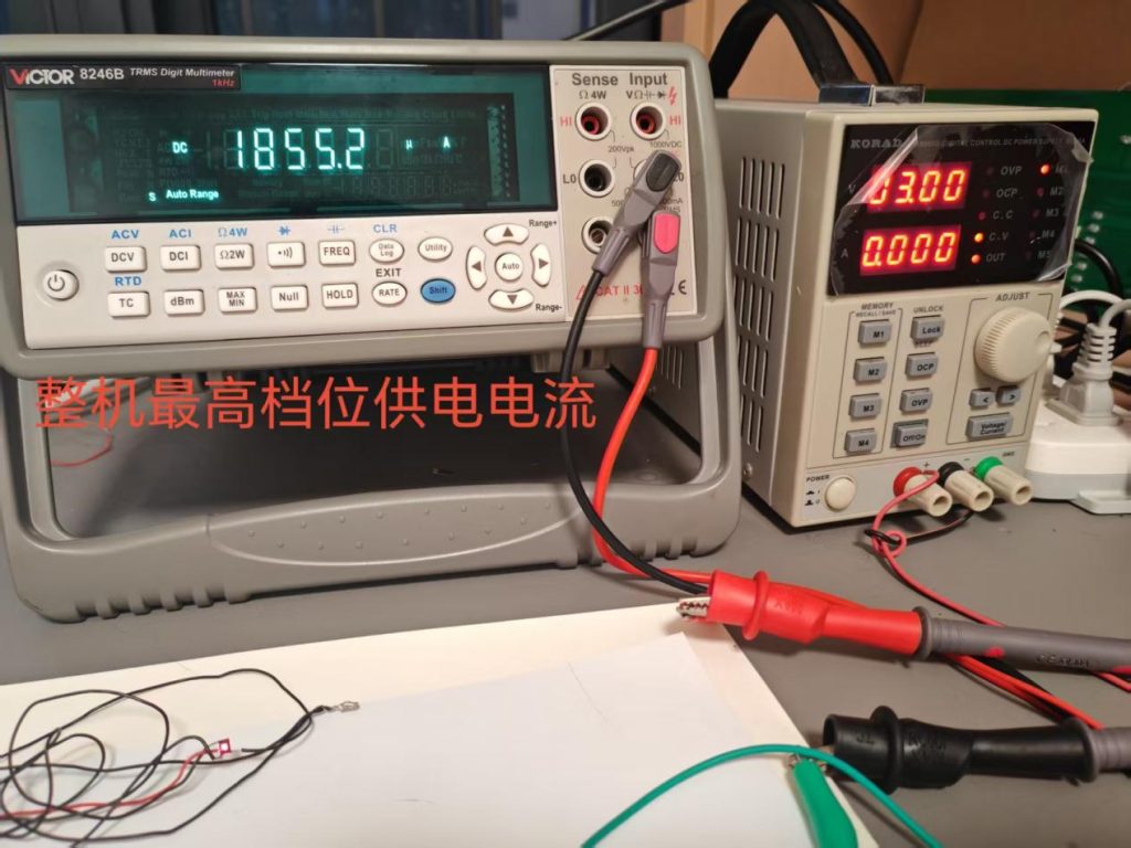
- Low-current constant-current driving and brightness stabilization
- Motion activation, auto sleep, and last-setting memory
- Battery contact stability under recoil and impact
- Power-consumption and brightness consistency across high- and low-temperature environments
Results Customers Can Perceive
Sharper Dot · Stable Brightness · Longer Runtime
The dot appears cleaner and sharper, remains more consistent across different brightness settings, and delivers reliable battery life even under low-current operation.
2. Optical Matching & Coating Design
Core Definition
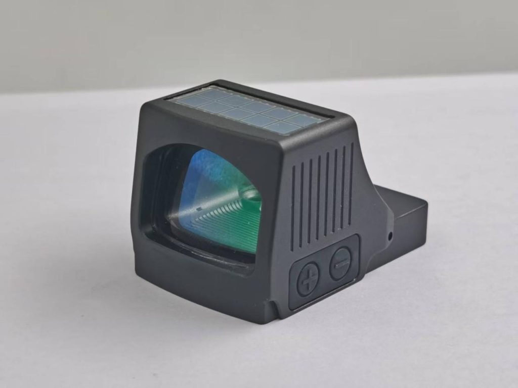
Once the illumination system has been defined, we determine the appropriate window size based on the sight’s actual mounting platform and viewing requirements. We then design the reflective lens material, optical surface geometry, glass cutting area, and spectral coating system.
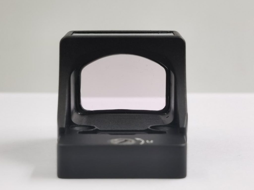
For enclosed red dot sights, the parallelism, anti-reflective coatings, assembly angles, and sealing stress of the front and rear protective windows must also be controlled as an integrated optical system.
Core Technologies
- Effective window sizing based on the intended application
- Selection of reflective lens material, thickness, and curvature
- Cemented reflective lens and aspheric reflective lens solutions
- Definition of the effective optical area and glass cutting position
- Control of cementing decentration and curing stress
- Matching the LED spectrum with selective reflective coatings
- Balancing light transmission, reflectivity, and color shift
- Suppression of parallax, edge distortion, and ghost images
- Control of window parallelism and wedge angle in enclosed sights
- High-transmission anti-reflective coatings and internal ghosting control
- Control of optical deformation caused by sealant shrinkage
Results Customers Can Perceive
Clearer Window · Lower Color Shift · Better Parallax Control
The viewing window appears clearer and more transparent, with less background color shift and edge distortion. The aiming dot also remains more stable when viewed from different eye positions.
 The reflector, LED spectrum and coating curve must be matched together. A brighter reflection does not automatically mean a better optical system.
 The reflector, LED spectrum and coating curve must be matched together. A brighter reflection does not automatically mean a better optical system.
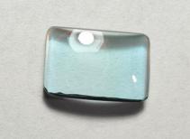

 Coated optical windows must balance selective reflection with high environmental-light transmission and controlled color shift.
- Optical alignment equipment verifies window angle, optical-axis consistency and the interaction between the emitter and reflector.
3. Precision Adjustment, Sealing & Structural Strength
Core Definition
Only after the electronic and optical systems have been finalized can the required adjustment accuracy, housing material, CNC dimensional tolerances, component-retention methods, and sealing elements be properly defined.
The mechanical structure does more than determine the product’s appearance. It must securely support the LED, circuit board, reflective lens, battery, and adjustment system while maintaining long-term functional stability.
Core Technologies
- Windage and elevation adjustment mechanism design
- Adjustment screw pitch and machining accuracy
- Click feel and movement-per-click control
- Matching of springs, spring plates, and preload structures
- Control of backlash and windage-elevation interaction
- Zero retention before and after recoil or impact
- Selection of 6061, 7075, and other structural materials
- Housing wall thickness, protective wings, and reinforcing rib design
- Secure retention of the reflective lens, LED, and circuit board
- Battery-contact preload and momentary power-interruption protection
- Selection of O-rings, sealing gaskets, and adhesives
- Design for waterproofing, fog resistance, temperature resistance, and corrosion protection
Results Customers Can Perceive
Accurate Adjustment · Reliable Zero · Durable Protection
Windage and elevation adjustments are smoother, more consistent, and more accurate. The sight continues to maintain zero and stable functionality after recoil, drops, and changes in environmental conditions.
 Adjustment accuracy, zero retention, structural strength and sealing are designed as one integrated mechanical system.
 Adjustment accuracy, zero retention, structural strength and sealing are designed as one integrated mechanical system.
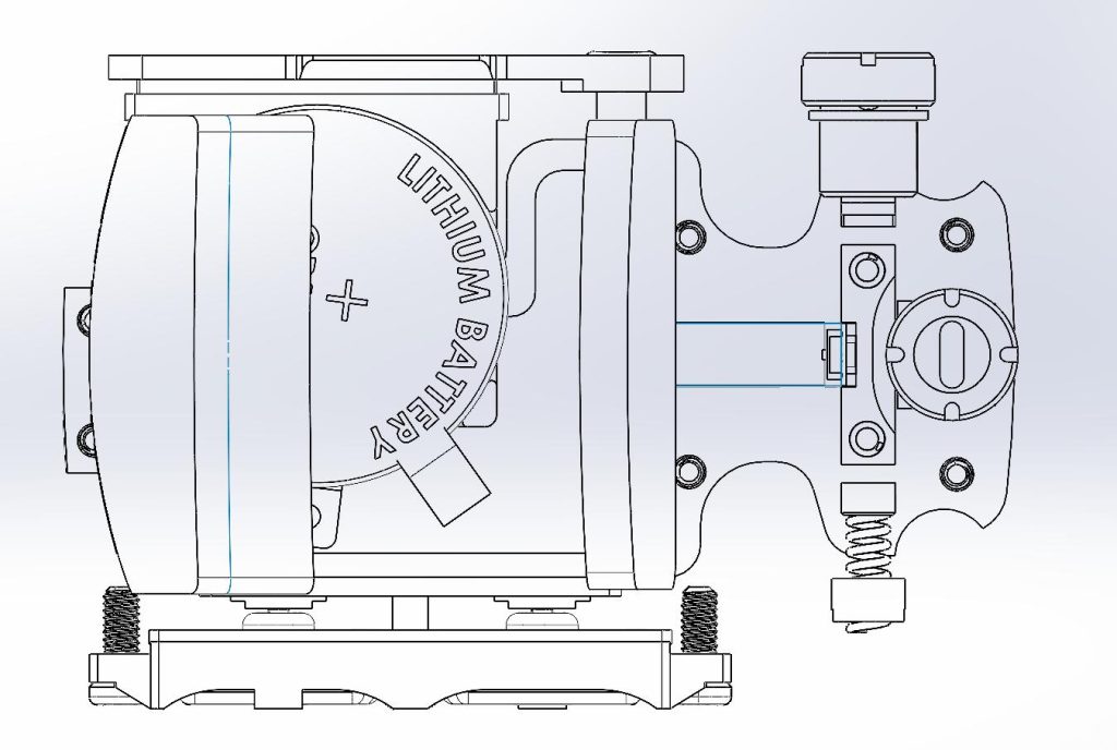
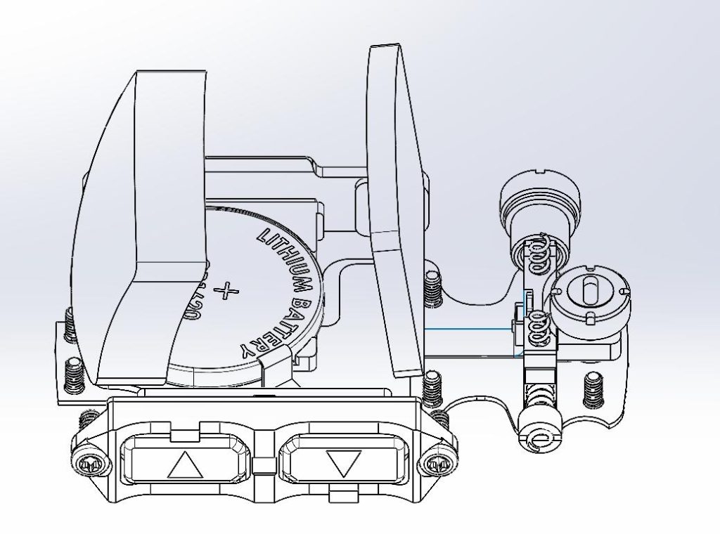
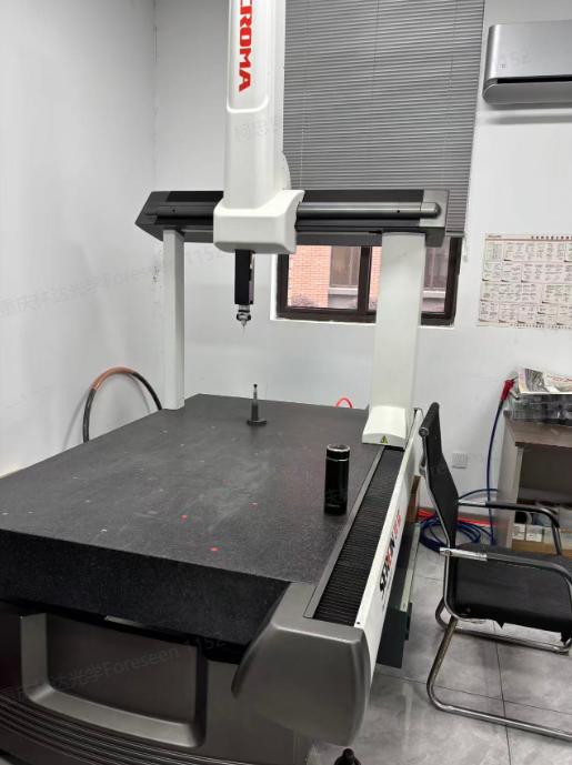
 Critical machined dimensions are checked against drawings to control adjustment alignment, component fit and sealing interfaces.
 A dedicated impact test rig subjects the sight to repeatable shock loads to verify structural integrity and zero retention.

4. Fast, Stable Low-MOQ Delivery Planning
Core Definition
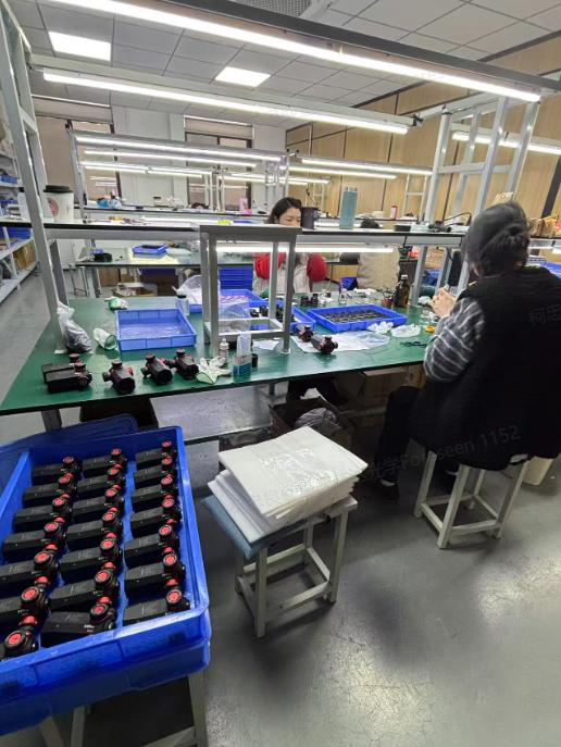
Fast delivery and low-MOQ production do not simply mean accepting small orders. They depend on mature product platforms, shared components, reusable manufacturing processes, and standardized inspection systems.
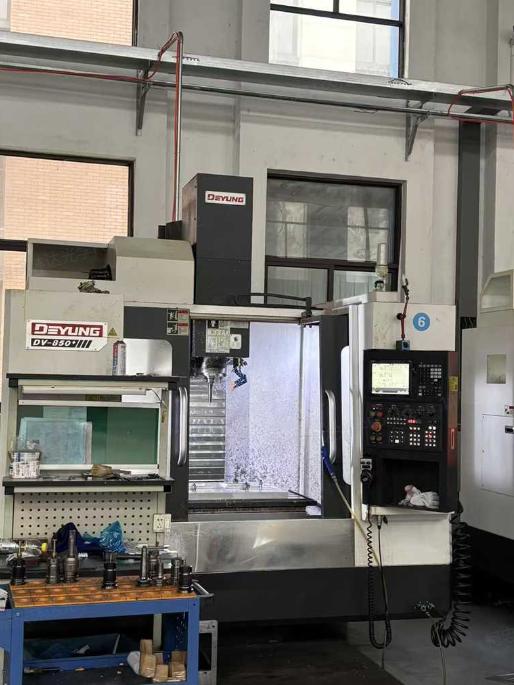
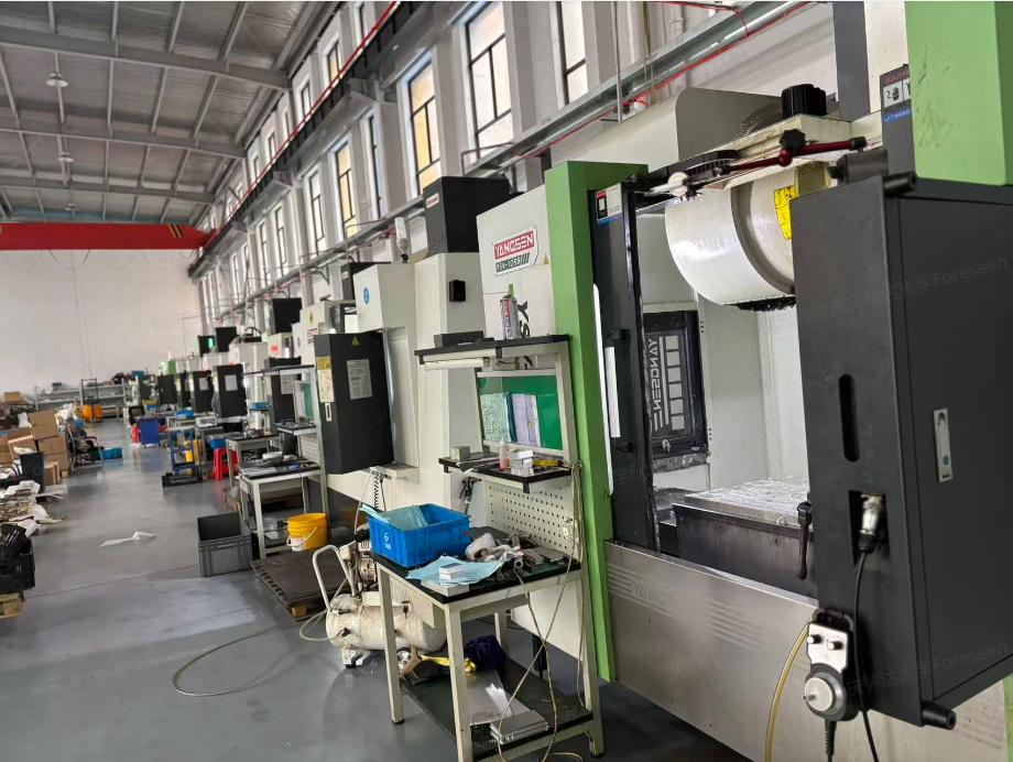
Once the electronic, optical, and mechanical solutions have been finalized, we further plan the BOM, machining processes, assembly sequence, inspection checkpoints, and inventory strategy. This allows the design to be converted reliably into both prototypes and mass-produced products.
Core Technologies
- Reuse of proven electronic and optical platforms
- Rapid exterior styling and structural-variant development
- CNC machining and fixture-sequence planning
- Assembly-sequence design for electronic, optical, and mechanical components
- BOM classification and supply-risk management
- Inventory planning for common LEDs, seals, and standard components
- Stocking of CNC semi-finished housings and universal mounting plates
- Dedicated assembly stations for small-batch production
- Rapid first-article approval and engineering-change management
- In-process inspection at critical manufacturing stages
- Preset inspection equipment and acceptance parameters
- Production-cycle and delivery-lead-time planning at the unit level
Results Customers Can Perceive
Faster Development · Lower MOQ · More Stable Delivery
Without bypassing essential validation procedures, we shorten the customization and development cycle, reduce the quantity required for the first production order, and improve consistency and delivery stability across subsequent batches.
How the Four Technologies Form a Complete Development Chain
| Development Stage | Key Elements That Must Be Defined First | Inputs Provided for the Next Stage |
| Step 1: Illumination System | LED spectrum, power consumption, dot shape, and brightness-control logic | Coating wavelength range, reflection efficiency, and optical window requirements |
| Step 2: Optical System | Window size, reflective lens, optical surface geometry, and coatings | Structural space, component mounting positions, and adjustment range |
| Step 3: Mechanical System | Adjustment mechanism, materials, tolerances, component retention, and sealing | Conditions for machining, assembly, and reliability validation |
| Step 4: Industrialization System | BOM, manufacturing processes, inspection, inventory, and production cycle time | Stable prototypes, low-MOQ production, and volume delivery |
From Emission to Mass Production
FORESEEN OPTICS does not build red dot sights by simply assembling readily available components.
We begin with the illumination system, develop the optical system around the characteristics of the LED, and then design the precision adjustment mechanism, CNC-machined structure, and environmental sealing around the electronic and optical requirements. Finally, through process planning, BOM management, standardized inspection, and inventory control, we transform the design into a product that can be reproduced consistently.
This complete control capability—from the light source to mass production—forms the foundation of our support for customized red dot sight development, low-MOQ manufacturing, and reliable long-term delivery.