1608–2026, A Technical Chronological Overview – Michael
This year marks my 18th year in the optics industry.
In many cultures, eighteen symbolizes “coming of age”: a point at which one moves beyond pure passion and curiosity, and becomes capable of bearing responsibility, understanding trade-offs, and knowing more clearly where a lifetime of effort should be invested.
For me, this is a personal optical coming-of-age gift—not a celebration of achievement, but a moment of reflection and reaffirmation: that I am willing to continue walking alongside optics, this ancient yet continuously evolving discipline, in the way of an engineer. It is precisely for this reason that I want to turn this coming-of-age gift into something to be shared—offered to everyone who is interested in the origin and development of binoculars.
Binoculars are far more than simply “two telescopes bound together.” They are a quintessential example of systems engineering. Every stage, from dual-channel collimation and magnification matching to aberration control in prisms and eyepieces; from the introduction of rare-earth materials and the uniformity of glass melting to coating technologies, sealing, assembly, dependability, and mass-production consistency—represents a challenge that previously required decades to overcome.
This chronicle begins with the emergence of the telescope itself and unfolds along more than four centuries of engineering evolution. It traces how the optical bottlenecks, structural challenges, and material limitations that once constrained binocular development were repeatedly broken through, accumulated upon, inherited, and redefined—and how, through the combined force of technology and manufacturing, they ultimately gave rise to today’s rich and diverse binocular systems, serving a wide range of applications.
I will try to avoid “legend-style” storytelling, and instead use the language of engineers: clearly explaining what the problem was, why it was difficult to solve at the time, where the critical breakthroughs came from, and how they reshaped subsequent design paths. My hope is that by the end, you will not only see the history of binoculars, but also understand the engineering logic behind them—and understand how the seemingly mature tool in our hands today gradually became possible, step by step.
1608–1662: The “Modern Framework” of the Refracting Telescope Takes Shape Over a Century
1608: As soon as the telescope appeared, “binocular viewing” became one of the first engineering challenges.
Around 1608, the telescope appeared in a form that was almost a “prototype tool.” It could see far, but it was far from stable, repeatable, or systematic. Interestingly, almost at the same time, the question of whether it could be used with both eyes was raised—not as an aesthetic preference, but as a natural demand of the human visual system. Using both eyes brings more comfortable viewing and a better sense of depth.
From an engineering perspective, however, “binocular viewing” was far more than simply placing two telescopes side by side. Suddenly, the challenge shifted from “making a telescope that forms an image” to making two optical systems with matching performance that can maintain their geometric relationship over time. This was the first real barrier in binocular development:
- The two channels had to be parallel and collimated. Otherwise, double vision and eye fatigue would occur—a problem that even today affects many binoculars after prolonged use.
- Magnification and image quality had to match. If they didn’t, the brain couldn’t fuse the images properly. Early estimates set the minimum requirement at no more than 5% difference between the left and right channels.
- Interpupillary distance (IPD) had to be adjustable and stable. This allows different users to observe comfortably. For example, as a Chinese user, 72 mm was enough for me, but one of my Dutch clients needed 78 mm for comfortable viewing.
These three constraints have guided the structural design, assembly, and manufacturing logic of binoculars for the past four hundred years—and even today, they remain the underlying rules of design.
1611–1662: Rapid Structural Iterations Define the “Usable Upright Terrestrial Telescope”
In 1611, Kepler proposed the Keplerian design with two convex lenses, laying the foundation for higher magnification and improved image quality. By 1617, the first recorded manufacturing of this design appeared, showing that the concept had moved from theory into practical reality.
Over the next few decades, the focus of engineering iterations was no longer simply “seeing farther.” The challenge became making a telescope stable and reliable for terrestrial use, particularly producing upright images.
- Around 1625, image-erecting elements were introduced.
- By 1645, a two-lens relay system for upright images was developed. (Although binoculars later switched to prism-based systems for erect images, this relay design continued to be widely used in rifle scopes.) This greatly improved the intuitiveness and usability of terrestrial observation.
- In 1662, the Huygens eyepiece appeared, introducing the concept of combining field and eye lenses, which allowed field of view, aberrations, and viewing comfort to be systematically controlled.
From an engineering perspective, by the late 17th century, a “framework” that would be repeatedly inherited had already taken shape:
Objective → (upright/relay system) → Eyepiece (with growing awareness of aperture and stray light control).
This framework was not yet a binocular, but it provided two key prerequisites for the future development of binoculars:
- The single-channel imaging path became stable and reproducible.
- Engineers could finally shift focus from “can it produce an image?” to “how to make it better and consistent?”
The true engineering history of binoculars could only begin after this stage—once the single-tube structure became reliably replicable.
1700–1758: Aberration Bottlenecks and the “Engineering Unlock” of the Achromatic Objective
Early core problem: Chromatic aberration locked the usable aperture, forcing a trade-off between resolution and light throughput.
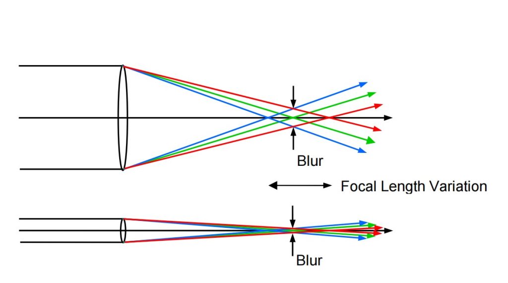
In the early 18th century, the main factor limiting telescope performance was not magnification, but chromatic aberration in the objective lens. In refracting systems, different wavelengths bend by different amounts, so red, green, and blue light cannot focus at the same point. The result was very direct: color fringes appeared around the image, fine details were swallowed by “color blur,” and the problem became worse as magnification increased.
At the time, without any achromatic solution, the only reliable engineering method to suppress this problem was to reduce the effective aperture—or, in practical terms, to limit the light beam. Once the aperture was reduced, aberrations appeared more controlled, but the cost was equally clear:
- Light throughput dropped (images became dim and low in contrast, especially in low-light conditions);
- The diffraction limit arrived earlier (the upper limit of resolution was lowered);
- Increasing magnification lost its meaning (what was magnified was blur and color fringes, not detail).
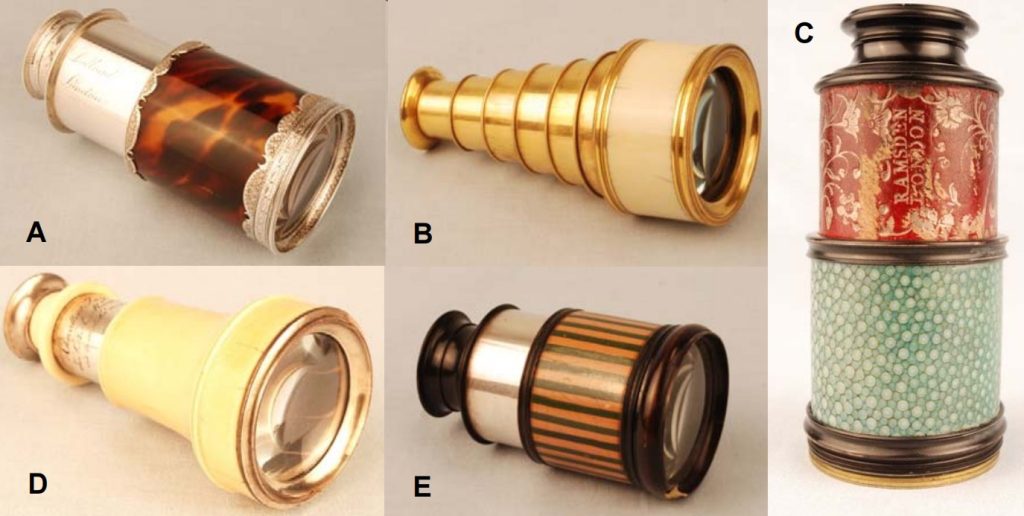
This is why many early handheld telescopes look carefully crafted, yet often have effective apertures of only a few tens of millimeters. It wasn’t that larger apertures were impossible—it was that making them larger didn’t make them usable. The image quality simply couldn’t support it.
At the same time, chromatic aberration also led to a typical structural side effect. To achieve a usable field of view and exit pupil, eyepiece elements in some configurations had to become disproportionately large, resulting in an awkward “small front, large rear” shape. In extreme cases, this even produced so-called reverse-conical telescopes. This wasn’t an aesthetic choice, but a direct structural outcome of beam control and aberration management: when the objective side was tightly limited, and the eyepiece side still had to “stretch” the field of view, the geometry naturally moved in a counterintuitive direction.
1733–1758: The Achromatic Compound Objective Emerges and Is Commercialized, Unlocking Performance from Its “Constrained State”
In 1733, Chester Moor Hall achieved achromatic correction by combining positive and negative lenses with different dispersion characteristics. This was a fundamental correction to the refracting telescope. Image quality was no longer preserved by “surviving through reduced aperture,” but by bringing different wavelengths back into alignment through materials and optical structure.
In 1758, the Dollond family secured the related patent and pushed the design into commercial production. Only then did its real engineering value begin to unfold:
- The upper limit of usable aperture was raised. Handheld telescopes could maintain acceptable image quality with objective diameters in the 25–50 mm range or even larger.
- Brighter and clearer images at the same magnification. Light throughput and resolution improved at the same time.
- A sharp increase in design freedom. Engineers could finally bring the trade-offs between magnification, field of view, size, and weight back into a controllable range, instead of being rigidly constrained by chromatic aberration.
In a technical chronicle, the engineering conclusion of this period can be stated very clearly:
Achromatic correction was not a gradual improvement, but an “unlocking of the performance framework.” It moved refracting systems from “maintaining usability by limiting aperture” to “achieving scalable performance through materials and structure.”
That said, optical breakthrough was only the first step. Once apertures increased, new bottlenecks appeared immediately—mechanical coaxiality, alignment stability, lens cell and tube design, and mass-production consistency became the next main battlefield. This is why the later engineering story inevitably shifts toward materials and manufacturing: without a more reliable structural system, the performance potential unlocked by achromatic optics cannot be delivered consistently.
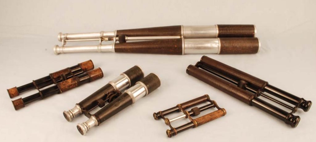
1750–1800+: Precision Brass Draw Tubes and the Era of “Glass + Brass” Mass Production
The significance of this stage lies in the fact that performance improvements in refracting telescopes no longer depended on optical design alone. For the first time, they were systematically supported by materials and manufacturing capability.
Achromatic optics raised the upper limits of aperture and image quality, but turning that potential into portable instruments that could be used reliably over time and produced with consistent quality at scale shifted the real battlefield to tube structure, coaxial stability, draw-tube tolerances, and assembly details.
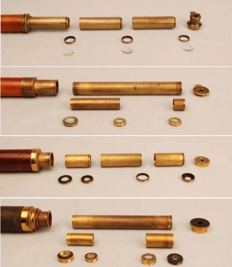
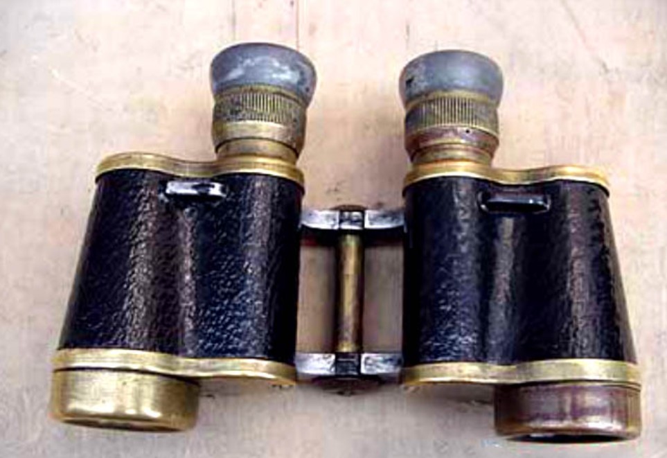
Around 1750: From Paper and Leather Tubes to Brass Components — Durability and Coaxiality Become Primary Metrics
Before the mid-18th century, many telescope tubes still relied on rolled paper and leather-wrapped construction. These methods have low barriers to manufacturing, but their engineering flaws are also quite obvious:
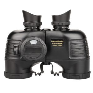
- Temperature and humidity sensitivity. They were particularly unsuitable for maritime use because of the deformation, cracking, and warping caused by moisture absorption.
- Insufficient geometric stability. Tube stiffness was limited, and even small external forces could cause optical axis misalignment.
- Uncontrolled interface precision. Joint tightness and concentricity varied widely, making stable alignment difficult to maintain.
For draw-tube telescopes, the structural challenges were even more concentrated. A draw tube is not considered successful simply because it can extend and retract—it must satisfy several conflicting engineering constraints at the same time:
- Smooth sliding, otherwise focusing and storage become frustrating;
- No self-sliding, where minor vibration causes the tube to collapse;
- No hinging at the joints, since section tilt leads to axis shift and image degradation;
- Strict coaxiality, because once magnification increases, image quality collapses immediately if alignment is lost.
These constraints made it clear that paper-and-leather systems were fundamentally inadequate for the goals of high performance and high reliability. A transition in materials was not optional—it was inevitable.
From 1750 Onward: Precision Brass Draw Tubes Mature — Multi-Section Telescopes Become Truly Reliable Products
The value of brass was not just that it was “stronger,” but that it enabled a much more controllable manufacturing chain. Thin-walled tubes could be produced through engineered processes with highly consistent geometry and surface quality. A typical production route was:
Sheet rolling → silver-solder seam closure → drawing through steel dies
This process delivered two key engineering benefits:
- High concentricity. The geometric axis of the tube became more stable, directly improving optical axis retention and assembly consistency.
- Controlled mating surfaces. Wall thickness, inner and outer diameters, and surface finish became repeatable, forming the basis for draw tubes that were smooth to slide, yet resistant to self-sliding.
By the late 18th century, multi-section draw-tube structures had matured. Manufacturers such as Dollond began offering three- and four-section draw telescopes as stable, commercial products:
- Significantly reduced collapsed length, making telescopes of the same focal length far more portable;
- Long-focus designs became practical, maintaining image quality without sacrificing portability;
- Structural systems began to standardize, with section interfaces, locking methods, and internal blackening becoming established “industry practices.”
From an engineering standpoint, the most important shift of this period was this: draw-tube telescopes were no longer artisan objects, but reproducible products. This laid the industrial groundwork for the assembly consistency required by future binocular systems.
Around 1800: Refining Assembly Engineering — Couplings, Stops, Lens Cells, Baffles, and Maintenance Become Part of the Product
Once telescope tubes entered the more precise metal era, the focus of competition quickly shifted from “can it be made?” to “can it be used reliably over time?”. This led to a series of seemingly minor, but reliability-critical, details gradually becoming standard features.
1) Coupling structures: from “screwed together” to “rigidly located”
- Early section connections often relied solely on end-thread engagement, making them prone to slight lateral movement under side loads. The improvement was clear: deeper thread engagement increased resistance to loosening and shear.
- Introducing a secondary shoulder contact allowed the connection to no longer rely entirely on threads, separating load-bearing from positioning, and significantly improving overall rigidity.
The goal of these changes was simple: make extended draw sections behave as closely as possible to a single continuous tube.
2) Stop structures: preventing over-extension, disassembly, and damage
- A common failure in draw-tube telescopes came from over-pulling or pulling past the tube’s limit. Stop pieces or limiting structures were a typical productization measure, preventing sections from fully disengaging and falling.
- They also prevented thread damage or splitting of thin-walled tubes.
- Essentially, they turned user errors into minor mishaps rather than catastrophic failure.
This was the first time engineering reliability explicitly entered telescope structural design.
3) Lens cells and retaining rings: from “holding the lens” to “mechanical reference”
Early lenses were often held with simple retaining rings, with the main concern being “don’t fall out”. Around 1800, lens cells began to take on a clear engineering role:
- Acting as mechanical references for the optical axis, controlling tilt and decentering;
- Allowing maintenance and disassembly without damaging the tube;
- Maintaining stable clamping under temperature and humidity changes, while minimizing stress to avoid lens deformation.
In essence, optical elements were elevated from “installed somewhere” to “installed in the correct position.”
4) Baffles and maintenance: stray light control becomes engineering
- As apertures grew and fields of view expanded, stray light could quickly reduce contrast. Lens mounts began to include dust covers, stop apertures, and improved diaphragm designs; internal tube surfaces gradually received light-absorbing treatment and blocking structures.
- These were not decorative, but engineered measures responsible for contrast and detail in dark areas.
According to research by FORESEEN OPTICS across multiple countries, we were surprised to find that many manufacturers worldwide still rely on this same level of technology today. Many binoculars in production continue to use these historical practices, demonstrating an astonishing stagnation in industrial evolution.
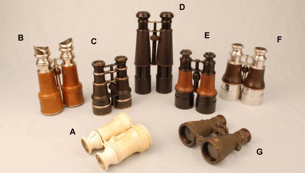
1823–Around World War I: Galilean Binoculars Mature from “Impossible to Mass-Produce” to “Opera Glasses / Field Glasses”
The key point of this period was not seeing farther, but the first wave of engineering that turned binoculars from concept into a commercial product. Challenges included: how to keep both optical channels geometrically aligned, how to synchronize focusing, and how to accommodate different interpupillary distances.
Galilean binoculars were able to scale up first for very practical engineering reasons: they had short structures, few elements, and no reliance on prisms, compressing the design challenges into a range that was manufacturable and assemblable.
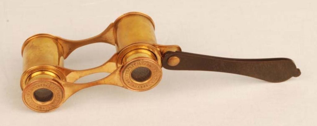
1823: Opera Glasses Establish a Structural Paradigm — Bridges, Linked Focus, and Adjustable Interpupillary Distance Standardized
Around 1823, the appearance of opera glasses was not about being “fancier,” but marked the first time binoculars became a structurally systematized product capable of large-scale production. The core paradigm can be summarized in three points:
1) Twin bridges turned “two tubes” into a structural reference
- The biggest problem with early binoculars was instability of the relative alignment between the two tubes. You could put two monoculars together, but their parallelism and coaxiality would drift over time and use. The introduction of a bridge effectively provided a unified geometric framework for the two optical channels:
- The tube center distance was fixed by the structural element;
- Assembly reference points for both channels were unified, making subsequent adjustment costs controllable;
- Structural rigidity increased, significantly reducing the occurrence of double images and tilt.
2) Linked focusing turned “adjust each tube separately” into a single action
- Binoculars that required separate focus for each eye could never become mainstream tools. The linked focus mechanism transformed the system from “two independent focusing systems” into one synchronized system, delivering clear engineering value: user effort was reduced to an acceptable level;
- Maintaining focus consistency between the two channels became easier;
- In production, controlling the tolerance of a single mechanism ensured a consistent user experience.
3) Adjustable interpupillary distance became a controllable mechanism
Binoculars must accommodate different users’ eye spacing. In the opera-glass era, this was engineered: the central hinge or bridge allowed the interpupillary distance to change, with friction or damping to make it adjustable yet stable.
Once IPD adjustment became a structural function instead of just “bending by hand,” binoculars truly qualified as consumer products.
Engineering significance of this stage in one sentence:
Binoculars had, for the first time, a structural paradigm suitable for mass production.
It did not rely on expensive materials or extreme optical design, but on structural references, linked mechanisms, and assembly logic, pulling binoculars from experimental or artisan creations into an industrial framework.
Even today, a very small number of opera-glass production lines remain worldwide, including FORESEEN OPTICS. However, they are no longer used as practical tools. Without prisms, this type of binocular is limited to around 3× magnification, suitable only for small-scale observation in theaters. Its continued existence owes more to elegant design than functional necessity.
Late 19th Century: Performance Improved, but Clear Limits Remained — Magnification and Field of View Constrained
The Galilean optical path imposed inherent limitations. It used a negative eyepiece and didn’t use prisms to erect the image. This made the system short and mechanically convenient, but it also created two hard constraints.
1) Magnification limits: usually around 3× for practical use
- As magnification increased, the Galilean field of view became narrower and edge aberrations harder to control. You could technically increase magnification, but users would experience “farther, but narrower, darker, and less clear” images. That’s why long-term products stayed in the low-magnification range: typical opera glasses were about 2.5×–3×.
- Larger “field glasses” could reach 5×–6×, but the field felt restricted.
This shows a typical engineering judgment:
When a design has inherent limits, incremental improvements—like better glass or more precise assembly—can improve the experience but cannot change the ceiling.
2) Field of view limits: exit pupil and eyepiece size
- In Galilean systems, the exit pupil is inside the tube, so the eye has to be very close.
- To get a larger field, the eyepiece must be bigger and more complex, which increases weight and cost and reduces the system’s main advantages: short, portable, and easy to use.
So Galilean binoculars stayed for a long time in a range that balanced usability and manufacturability, becoming typical tools for opera, ceremonial use, and short-range observation.
Material milestone: aluminum and early lightweight design
By the late 19th century, lighter materials started to appear for structural parts. The idea was simple: as binoculars moved from indoor consumer items to portable outdoor tools, weight and durability became key design factors. Lightweight didn’t mean “thin”; it meant choosing materials and structure together to reduce weight while keeping stiffness. This direction would expand greatly in the 20th century.
1854–1907: The “Decisive Technology Chain” of Porro Prism Binoculars — Invention Alone Isn’t Enough; Glass, Precision, and Systematic Manufacturing Matter
If the previous stage (opera glasses / Galilean binoculars) solved “can binoculars be mass-produced?”, then porro prism binoculars tackled “can binoculars become high-performance tools in the modern sense?”. They pushed binoculars beyond low magnification, short-range, ceremonial use, into a mainstream path of higher magnification, larger objectives, wider fields of view, and long-term portable use.
The point most easily misunderstood is this: **the Porro prism was invented in 1854, but it did not immediately lead to widespread modern binoculars. **The key in engineering history lies in the next 40 years: without suitable materials and manufacturing, all designs remained paper victories.
1854: The Porro Prism Provides the Optical Key to the “Modern Binocular Layout” — Upright Image, Folded Path, and Stereoscopic Depth All at Once
In 1854, Italian engineer Ignazio Porro proposed and promoted an upright, folded optical system based on right-angle prisms—later known as the Porro prism. Its engineering value was not a single improvement, but a system-level redesign:
- Upright image: no longer relying on long erecting lens groups, which would significantly increase system length;
- Folded light path: overall length could be reduced without sacrificing focal length;
- More practical objective spacing: the Porro layout naturally allows a wider objective baseline, improving depth perception and distance judgment—this is a fundamental upgrade to binocular usability.
From an engineering perspective, the Porro prism untied a long-standing contradiction: in the past, achieving an upright image and good image quality meant accepting systems that were long, heavy, and difficult to align. Now, for the first time, a structure that was short, powerful, and optically robust became possible.
But possibility is not the same as a product. What truly determined the course of history was whether the manufacturing chain could deliver the precision this optical layout demanded.
Why the Breakthrough Waited Until Around 1894: Prisms Pushed Material and Precision Demands Beyond What Industry Could Reliably Deliver
At first glance, the Porro design looks like a simple replacement of lenses with prisms. In reality, the engineering difficulty increased. The reasons are straightforward:
- The optical path is folded and extended inside the prism. Any glass inhomogeneity—such as striae, internal stress, or refractive index gradients—is amplified and shows up directly as image degradation.
- Prism angles are extremely sensitive. Errors of only a few arcminutes can cause exit pupil clipping, increased astigmatism, and make binocular collimation difficult.
- Assembly and stability are harder. Prisms require stable and repeatable positioning and clamping; even small shifts can lead to optical axis drift and double images.
In other words, prism binoculars pushed the industry from “being able to grind lenses” to “having to reliably produce homogeneous optical glass, high-angle-accuracy prisms, and controlled assembly processes.” Without this full set of industrial capabilities, the Porro layout could only exist as prototypes or expensive, low-volume products.
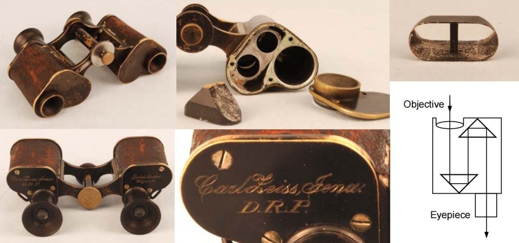
1894: The System-Level Victory of Zeiss × Schott × Abbe — Material, Design, and Manufacturing Converge into Modern Binocular Industry
In 1894, Carl Zeiss (Jena) began manufacturing prism binoculars, explicitly based on the design framework of Ernst Abbe. This moment is considered a milestone not because “a prism binocular was finally made,” but because it marked the establishment of a new engineering paradigm:
- Schott provided optical glass with controllable quality, bringing glass homogeneity and batch consistency into an industrial process;
- Abbe’s optical design methods and tolerance philosophy allowed systems to maintain performance even in the presence of manufacturing errors;
- Zeiss’s machining and assembly systems made collimation, sealing, and batch-to-batch consistency repeatable processes rather than individual craftsmanship.
Records from the Smithsonian directly note that Zeiss began producing prism binoculars in 1894 based on Abbe’s designs, and that prototype instruments around 1900 already showed the maturity of this industrial approach.
In a technical chronicle, this period can rightly be described as a textbook case of engineering collaboration: a single invention (the Porro prism) does not automatically change the world. What truly changes the world is when materials and manufacturing turn an invention into a stable, repeatable product system.
1897–1907: Roof Prism Designs Emerge and Quickly Diverge — From “More Compact” to “Harder to Build,” New Engineering Trade-Offs Appear
After prism binoculars matured, the next natural step was a more compact, more linear layout: the roof-prism design. From the very beginning, however, the roof-prism path came with new engineering costs:
- Certain surfaces in roof prisms require mirror coatings, unlike Porro prisms that rely mainly on total internal reflection. This directly introduced issues of coating quality and long-term durability.
- Roof prisms inherently introduce phase effects that reduce image contrast. Fully solving this problem required phase-correction coatings, which would only become practical and widespread much later—this is a clear setup for the next chapter of the engineering story.
On the timeline, sources such as Wikipedia commonly trace the proposal of the Schmidt–Pechan roof prism to 1899, and identify the Abbe–König roof prism as another main route. The key patent and protection milestones associated with the Abbe–König design, particularly those linked to Zeiss, were established progressively in the early 20th century.
1908–1925: Prism Binoculars Move Toward “Structural Standardization” — Alignment References, Prism Mounts, and Focusing Systems Begin to Stabilize
By the 1890s, prism binoculars had already proven that the optical route was correct. But there was still a critical step before reaching a truly “modern product system”: getting the optical design right did not mean the product would be stable, durable, and repeatable.
In the early 20th century, engineering focus shifted from “having a prism solution” to “how to manufacture and use prism binoculars reliably over time.”
1) Prism mounting: from “placing the prism inside” to controlled prism-seat systems
Using early Zeiss Porro binoculars as an example: in products around 1895, prisms were mounted in machined recesses inside the body and held in place by end caps. At the prism apex, soft materials (such as cork) were used to provide both cushioning and positioning.
This structure shows that engineers had already realized an important point: a prism is not something you simply press into place. Force distribution, positioning accuracy, and edge protection all had to be considered together.
At the same time, these early designs reveal a typical early-stage trade-off: the two Porro prisms were placed far apart inside the body. In modern binoculars, the two prisms are placed as close as possible, sometimes even in contact, to free up space for larger objective lenses.
- This is a classic engineering evolution path: early designs prioritize “easy to mount and easy to align”;
- Later designs prioritize compactness, larger objectives, and easier sealing;
- Structures gradually converge toward the stable concept of a prism housing.
2) Focusing systems: from individual focusing to more efficient linked mechanisms
Another feature of the same early products is that focusing was done by adjusting each eyepiece separately (individual focusing). From an engineering point of view, this made it easier to ensure that both optical channels were properly focused.
However, it placed a heavy burden on the user and was not well suited for fast observation.
As a result, during 1908–1925, the industry increasingly moved toward writing faster and easier use into the structure itself. Linked focusing systems and clearer adjustment procedures gradually became the mainstream direction for consumer binoculars. This shift also laid the foundation for binoculars to become true field tools later on.
3) Body materials and machining: aluminum alloy castings plus machined seats replace the “all-brass” mindset
Early prism binoculars already showed the combination of cast bodies with machined critical surfaces. This marked a move toward a more modern manufacturing organization:
- the body serves as the main structural reference;
- prisms, objectives, and eyepieces are assembled around that reference;
- alignment relies less on individual craftsmanship and more on fixtures, references, and defined processes.
1920s: Exploration and Elimination of Prism Variants — “Flattening” Was Attractive, but the Engineering Cost Was Too High, and the Paths Eventually Converged
Once the Porro route was firmly established, engineers naturally asked a second question: can binoculars be made thinner, flatter, and more pocket-friendly?
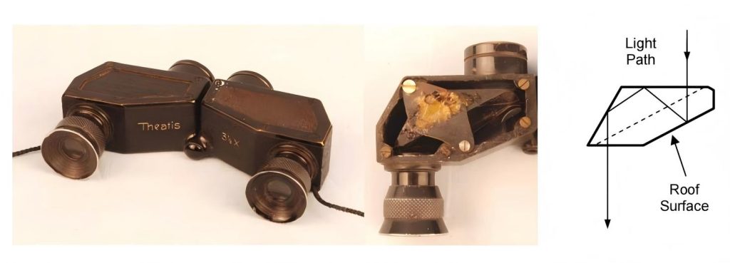
This led to the exploration of multiple upright prism systems with roof surfaces, all aiming to push compactness further. The paper provides a key clue here: the Leman (Sprenger–Leman) and Möller routes were representative of this “flattening” idea, but none of them ultimately became mainstream systems.
1) Roof surfaces enter binoculars: from pentaprisms to the more compact Leman (Sprenger–Leman) design
According to the paper, upright prism systems with roof surfaces entered binocular design around 1897, initially in pentaprism configurations. Later, more compact solutions such as the Leman (or Sprenger–Leman) prism appeared.
The engineering intent was clear:
- use roof surfaces to achieve the required out-of-plane reflections;
- complete image erection while shortening the structure and flattening the external shape;
- accept the cost of a more complex light path and much higher sensitivity to prism geometry and alignment.
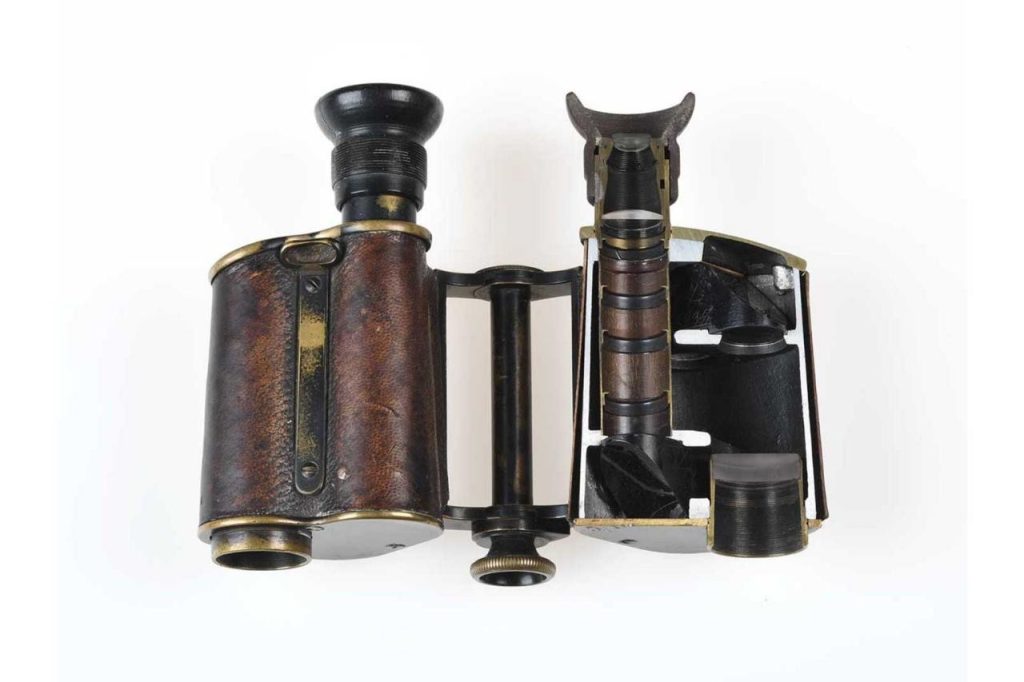
The paper gives a very concrete example: the late-1920s J.D. Möller “Theatis 3½×” Leman-prism binocular (Figure 18), which achieves an upright image through four reflections.
The existence of such designs shows that the industry in the 1920s seriously explored thin binoculars as real products, not just concepts.
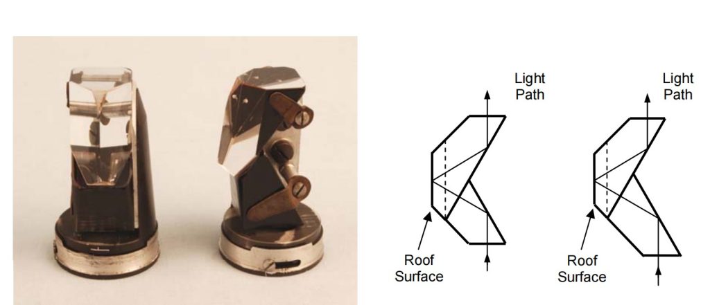
2) Abbe–König: an early-1900s upright system with no lateral axis offset, and a key ancestor of modern roof prisms
The paper also emphasizes that the Abbe–König prism appeared very early in the 20th century. Its key feature is that it produces an upright image without introducing lateral displacement of the optical axis.
It is explicitly identified as a predecessor in the development chain leading to the Pechan roof prism (aka the Schmidt–Pechan).
- In a technical chronicle, this can be written as a point of path convergence: the 1920s saw many competing branches;
- Only those that could meet compactness, manufacturability, alignability, and long-term stability at the same time survived;
- the Abbe–König / Pechan branch ultimately fit industrial production better.
For this reason, Abbe–König prisms are still used today in some large-aperture roof-prism binoculars that do not pursue extreme compactness. Foreseen Optics continues to maintain this product line.
Its advantages are practical and engineering-driven: the slight axial offset allows objective diameters up to 60 mm without interpupillary-distance interference, and its strong light-throughput capability delivers a clear increase in image brightness.
3) Möller Prism: a More Aggressive “Six-Reflection” Flattening Approach — Elegant Structure, High Engineering Cost
The paper describes the Möller prism very directly: it produces six internal reflections and allows for a “flat roof-prism binocular.” Its key feature, as with other roof designs, comes from the roof surfaces providing out-of-plane reflections.
A concrete example from the mid-1920s is the J.D. Möller “Tourox 8×” (Figure 20). Its prism system consists of two cemented prisms, held with spring clips, forming the six-reflection light path.
From an engineering perspective, the conclusion is clear:
- More reflections and a more folded light path make the body thinner;
- But each added reflection and critical surface increases sensitivity to prism geometry, angles, coatings or total internal reflection, assembly alignment, and long-term drift;
- The manufacturing requirements often exceeded the industrial capabilities of the time, making it difficult to become a mainstream, reproducible solution.
4) Why these designs disappeared: not a failure of concept, but a failure of engineering economics
The paper concludes that Leman and Möller prisms are rarely used today.
In chronicle form, this can be summarized in one sentence:
The “flattening” routes of the 1920s proved that binoculars could look elegant, but the industry ultimately chose paths optimizing performance—reliability—manufacturability simultaneously.
- Therefore, engineering branches converged into two main streams:
- Porro (Paul-style): relatively wide structure, high optical efficiency, and lower manufacturing requirements;
- Modern roof systems (Abbe–König / Schmidt–Pechan chain): more compact, but requiring higher coating quality and precise assembly—capabilities gradually realized over the following decades.
1926–1939: On the Eve of Acceleration — “Field of View Revolution + Light Metal Bodies + Single-Layer Coatings” Push Binoculars into the Modern Industrial Pace
If the late 19th century to post–World War I prism binoculars can be called the “route establishment period,” then 1926–1939 marks the “engineering realization period.” During this phase, the industry shifted its focus from simply “can it be made” to “make it lighter, faster, more consistent, and comfortable to use,” and began leveraging materials and processes to fully extract optical potential. It also laid the foundation for the explosive wartime production and standardization of the Second World War.
1) Field of View and Comfort Became Primary Metrics — Wide-Angle Eyepieces Go Industrial
A clear turning point in binocular experience occurred in the early 20th century: users were no longer satisfied with simply seeing clearly; they began to demand a sense of openness, natural viewing, and efficient scanning. ZEISS milestone records mark 1917 as the introduction of wide-angle eyepieces into binocular design, which can be seen as the starting point for industrial adoption of wide fields of view.
By 1926–1939, this development continued to advance in engineering terms, reflected in three key points:
- Eyepieces evolved from “basically usable” to fully system-designed wide-field optics: Wider fields required more complex aberration management (edge astigmatism, field curvature, distortion). Achieving this was not just about swapping a lens; it involved integrating eyepiece design, aperture placement, exit pupil, and baffling into a coherent tolerance chain.
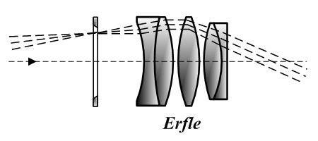
- Typical wide-field optical designs came from military demands: For example, Erfle-type wide-field eyepieces often featured 5–6 lens elements and apparent fields of 60–70°, originally developed for World War I military applications.
- Engineering cost was high: Increasing the field of view made eye relief, diopter range, baffle structures, and black-level control more sensitive. In binoculars, the left-right consistency and assembly stability directly determined whether the instrument felt comfortable.
2) Lightweighting Is No Longer Just “Shedding Weight” — It Becomes a Change in Manufacturing Organization: Light Metal Bodies Enter the Mainstream
One of the most important structural changes of this period was the shift in housing materials from brass/zinc alloys to light metals. ZEISS records clearly indicate that from 1933 onward, light metals began to replace brass and zinc in main body designs.
The engineering significance behind this goes beyond simply reducing weight; it represents a shift in the industrial approach:
- Consolidated structural reference points: Light metal castings (or die-castings) are better suited for integrated housings, with critical mounting surfaces machined afterward — significantly improving batch consistency and assembly efficiency.
- Improved stiffness-to-weight ratio: The fundamental challenge in binoculars is maintaining long-term geometric stability between the two optical channels. Light metals are not inherently stiffer, but with proper ribbing and integrated structures, they achieve sufficient stability at lower weight.
- Human factors and portability begin to influence optical design: Once weight is under control, designers gain more freedom in aperture, field of view, and body proportions, allowing products to become truly suited for long-term use rather than being forced into overly long, heavy forms just to satisfy optical requirements.
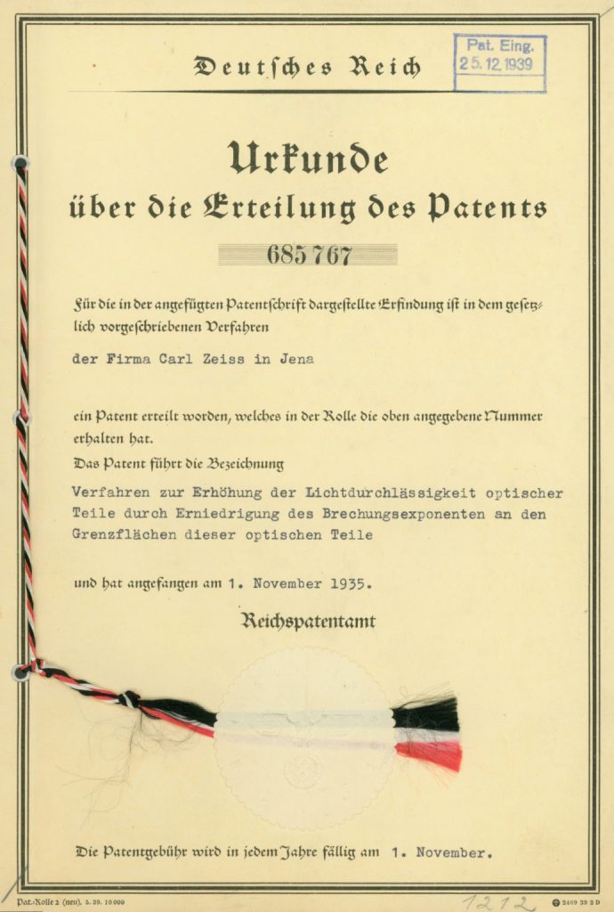
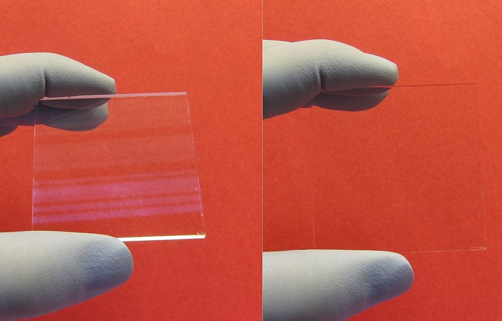
3) 1935: Single-Layer Anti-Reflection Coating Emerges — Enabling “More Glass, Higher Contrast” in Modern Optical Designs
In 1935, Alexander Smakula at ZEISS introduced the T anti-reflection coating, which the official milestones describe as significantly increasing binocular light transmission (ZEISS notes a “50% improvement”).
Broadly speaking, optical history also marks 1935 as the key point for interference-based anti-reflection coatings.
From an engineering perspective, AR coating brought more than just “a bit more brightness.” It enabled three deeper advances:
- Contrast and glare control reached a new level: Subjective clarity in binoculars depends heavily on micro-contrast. Coatings made internal reflections and ghosting more manageable.
- Design freedom expanded: With reduced reflection losses, engineers could confidently use more complex eyepiece and correction groups to improve field of view and aberration control, without “complexity leading to dimmer, hazier images.”
- Manufacturing consistency and durability became a new battleground: Coating is not just “put it on”; it introduces film thickness control, substrate cleanliness, environmental stability, and long-term durability as a new set of critical quality factors.
4) Assembly & Alignment Consistency: From “Can Adjust” to “Can Adjust at Scale” — Tools, Processes, and Serviceable Structures Mature
Between 1926 and 1939, there was another, less visible but equally critical trend: engineering the assembly and alignment process. The fundamental constraint of binoculars is parallelism and matched magnification between the two optical channels — otherwise, users experience double vision and fatigue. This cannot rely on “a master craftsman’s feel”; it must be absorbed into processes and structural design. SPIE papers also emphasize that binoculars are far more complex than monoculars, with alignment and magnification matching as the core engineering challenge.
During this period, the industry generally formalized the following mechanisms into repeatable, serviceable structural language (key points for engineering explanation in exhibits):
- Controllable collimation methods: Achieved via prism micro-adjustments (tilt, shims, set screws) or eccentric rings on objective lenses, providing reversible and recordable alignment paths.
- More standardized central focusing mechanisms: Center focus wasn’t new, but it gradually became the main user experience. It required rigid bridge structures, durable helical threads, precise clearances, and consistent low-temperature feel — otherwise users perceive the binoculars as “loose, sloppy, or drifting.”
- Serviceability integrated into structural design: Prism covers, focusing assemblies, and eyepiece bridges began to function more like modules, enabling batch maintenance and re-alignment.
1940s: Engineering Leap from “Functional” to “Scalable, Reproducible, and Field-Serviceable”
If the 1930s set the optical design and structural form of binoculars, the core contribution of the 1940s was turning “high performance” into something mass-producible, consistent, and maintainable in the field — arguably the most difficult and valuable step from an engineering perspective.
1) Anti-reflection Coatings Move from Lab to Production: From “Just Apply” to “Apply Consistently”
In 1935, Alexander Smakula at ZEISS developed and patented the T-type anti-reflection coating, raising transmittance and ghosting control for multi-element binoculars to a new level. For some years, this technology remained a military secret (roughly until 1940).
By the 1940s, the real challenge shifted to engineering reproducibility:
- Process consistency: Single-layer MgF₂ coatings are theoretically simple, but achieving stable thickness and uniformity across batch lenses required strict control of jigs, mounting methods, evaporation source stability, and process monitoring (even if just via witness plates, color comparison, or spot transmittance checks).
- Durability and maintainability: Early AR coatings were relatively fragile. In wartime conditions (dust, salt spray, frequent cleaning), coating failures directly impacted lifespan. This era introduced a system-level view linking coating, cleaning, and protection, laying the groundwork for later, more robust multilayer coatings.
- Quantifiable performance gains: A single MgF₂ layer could reduce reflection from ~4% per surface to ~1%. In multi-interface binocular systems, the cumulative effect was substantial, reducing stray light and improving contrast.
This is what I call “war-driven catalysis”: military pressures forced the industry to treat coatings not as optional enhancements but as standardized components, managed with engineering metrics such as transmittance, reflection, wear resistance, and batch consistency.
2) Standardized Assembly & Collimation: Treating Binocular Alignment as a Hard Requirement
Another critical lifeline for military binoculars was optical axis consistency and collimation quality. This directly determined whether long-term observation caused fatigue, “dizziness,” or hindered rapid target acquisition on moving platforms.
● The engineering trend in the 1940s was to shift collimation from “craftsman skill” to “repeatable jig-based processes.” Specialized calibration rigs, collimators, and parallel light tubes allowed the vertical alignment, tilt, and axis deviations of both barrels to be measured and adjusted systematically.
● Structurally, features that facilitated fine-tuning became widespread: eccentric rings for Porro binoculars, micro-tilt prism mounts, and similar mechanisms were all designed to absorb assembly errors and allow post-assembly correction. These adjustment logics remain standard in modern binoculars.
● Standardization also enabled a stronger quality feedback loop: products that didn’t meet alignment standards were not merely “good enough to see,” but had to be returned to the workstation for proper adjustment.
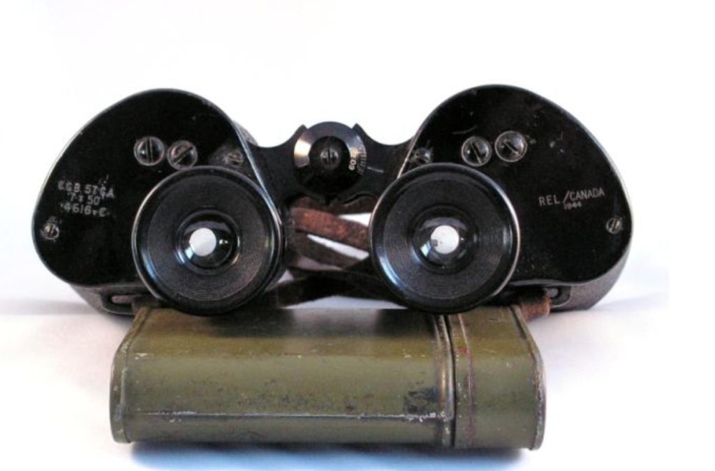
3) Wartime Systematic Manufacturing: Codes, Supply Chains, and the Dawn of Traceability
One often-overlooked detail is that war pushed the optical industry into large-scale, systematic production management for the first time. For instance, German military factories were assigned three-letter codes to reduce identification risk and streamline supply chain management and traceability (e.g., Zeiss “blc,” Leica/Leitz “beh”).This “mark—batch—repair/replace” logic later evolved into the civilian-era quality management mindset.
China: From Wartime “Repair System” to “Independent Production” — The Engineering Origins of the 6×30 Binocular at the 22nd Arsenal
During World War II and the War of Resistance, China began producing binoculars domestically. This was not a “start from zero to build a new binocular,” but a classic engineering path: first systematize repair capabilities, then turn the knowledge and processes gained from disassembly and repair into manufacturing ability.
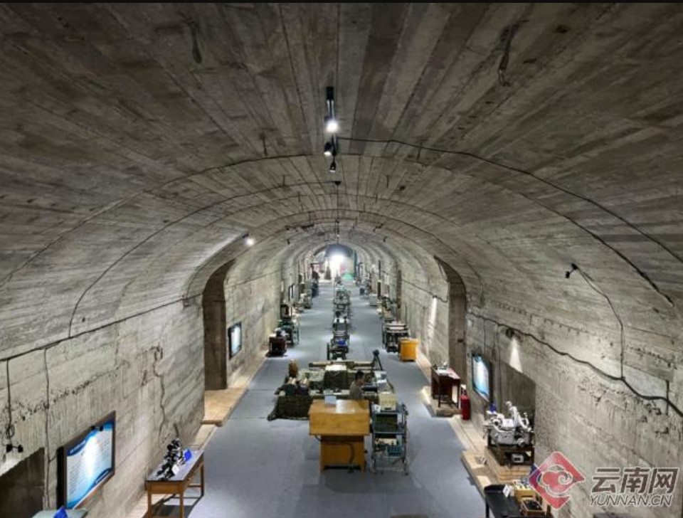
1) Establishment Path: From “Military Optical Repair Workshop” to Dedicated Optical Arsenal in Kunming
According to wartime military-industrial records in Kunming, the Ministry of Military Administration began building precision measurement systems in 1934 and first set up temporary repair workshops to handle maintenance of existing military optical equipment. Instruments, tools, and semi-finished parts were ordered from Zeiss in Germany, and Zeiss technician Jakob was invited to guide the workshops.
After the July 7 Incident, the optical repair system was relocated to Chongqing. However, frequent air raids and limited transport and construction conditions led to a final decision to move the facility to Kunming. In January 1938, the factory was built in Liuba, southern Kunming, and officially established in January 1939 under the name “22nd Arsenal.”
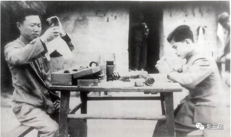
2) Key Milestone: April 1939 — Successful Prototype of the 6×30 Binocular, a Proof of China’s Domestic Military Production
The same historical records clearly state that on April 29, 1939, the 22nd Arsenal successfully produced China’s first 6×30 binocular.
● From an engineering perspective, this milestone was more than just “making a binocular”; it proved that, even under wartime conditions, China had established the critical capability loop required for binocular production: the optical axis alignment and collimation of the dual-channel system could be achieved and verified.
● The pairing, assembly, and processing of objective lens—prism—eyepiece could be completed entirely in-house.
● Production and inspection had moved beyond mere “repair” and entered a replicable “manufacture—test—rework” workflow.
3) Technical Support and Knowledge Sources: German Equipment/Technicians + “Benchmarking-Based Copying” of International Optics
The “technical sources” at this stage reflect a combination typical of wartime industry:
● German input (key processes and equipment): The early repair system at the 22nd Arsenal relied on tools and semi-finished components ordered from Carl Zeiss in Germany, and Zeiss technician Jakob was hired for guidance. This served as a fast track for introducing optical processing and assembly expertise into China.
● Benchmarking against international models (using products as teaching tools): Beyond binoculars, the factory also trial-produced German-style mortar sights, French artillery sights, and Swiss Wilt-type 80 cm reflecting rangefinders. This “war-driven, benchmark-guided” approach essentially imported structure analysis, process replication, and inspection standards all at once.
● Personnel and process organization (formation of a domestic engineering team): Historical materials note that the wartime optics sub-factory was organized by Zhou Zixin, with Gong Zutong handling optical design, Jin Guanglu responsible for precision engineering, and Peng Mingjing in charge of process organization, assembly, and development, culminating in the 6×30 prototype in April 1939.
4) Foundational Significance: What This Laid for China’s Later Military and Civil Binoculars
The wartime system left a foundational legacy for China’s subsequent binocular production—both military and civilian. Its core value was not any single model, but a set of enduring engineering assets:
- Industrial geography and organizational structure: In 1941, the 22nd Arsenal moved to Zhongtan, Haikou, dedicated to binocular production. In 1942, it merged with the 51st Arsenal to form the 53rd Arsenal under the Ordnance Department, combining optical instruments and machine gun production. This significantly improved both capacity and organizational capability.
- Integrated “repair–manufacture–trial production” chain: The pathway of first repairing, then copying, and finally trial-producing new military optics established a stable mechanism for the continuous iteration of optical military products.
- Process and talent continuity: Under wartime pressure, skilled teams, assembly methods, and inspection practices were developed, forming the “first-generation” backbone of China’s modern optical industry. This would later serve as the foundation for military and civilian expansions from the 1950s to 1980s.
- Postwar factory lineage: Historical records show that after 1950, the factories were taken over by the PLA, and the optical plants continued to evolve under the “22nd Arsenal” structure. This continuity explains why Kunming and Haikou became key hubs for China’s binocular industry and later supported the establishment of major PLA optical factories, including the 308, 338, 228, and other optics factories ending in “8.” Core personnel at FORESEEN OPTICS all come from the 308 Arsenal.
1950–1969: Expanding Materials and Roof Prisms Reshape Binoculars — Two Postwar Mainlines
In the two decades after the war, progress in binoculars no longer relied on “making structures more complex” to push performance. Instead, two more effective paths advanced in parallel: broadening material options and commercializing compact (roof-prism) designs. The first gave designers more leverage over aberration control through glass choice; the second turned the desire for “thinner, straighter, more portable” into deliverable products.
1) Rare-earth (lanthanide-based) glass expansion: high refractive index + low dispersion enters systematic use
The real limitation in optical design isn’t that aberrations exist—it’s that there are too few usable material points. Traditional crown/flint glasses offered limited options on the Abbe diagram, so aiming for shorter, more compact designs with wider fields often meant uncontrollable aberrations or a dramatic increase in lens count.
Postwar material developments addressed this: rare-earth doped glasses (lanthanum oxides, etc.) with high refractive index and low dispersion were introduced at scale and became an accessible material family by the 1950s. Their history traces back to systematic exploration of rare-earth glasses in the 1930s, reaching widespread engineering application in the 1950s.
Engineering benefits were immediate:
● More compact systems with the same image quality: higher refractive index reserves allowed more freedom in curvature and lens spacing, so eyepieces and correction groups no longer had to be “stretched” for tolerance.
● Better control of chromatic and edge aberrations: with more high-n, acceptable-v material points, designers could achieve cleaner image quality with fewer structural compromises—laying the groundwork for later ED/HD optical lines.
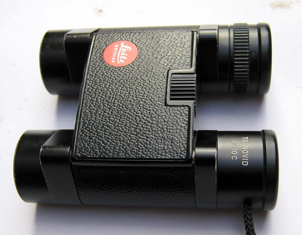
2) Commercialization of roof prisms: Trinovid 1958 marks the reproducible compact path
Roof prisms were not a new concept, but their adoption had long been limited by engineering challenges: prism angle precision, assembly stability, and reflection/surface quality sensitivity. Without a capable manufacturing chain, the “compact advantage” of roof prisms was offset by degraded image quality and consistency.
The 1958 launch of the Trinovid series was a key milestone in bringing roof-prism binoculars into commercial production. It used the Uppendahl prism system and internal moving lens groups to achieve central internal focusing, allowing focusing without changing internal volume, and facilitating later sealing and waterproofing developments.
From an engineering perspective, Trinovid’s significance lies in achieving three things simultaneously:
● Compact form: the roof-prism structure produced straighter, thinner bodies for more natural handling and portability.
● Internal focusing as a reproducible, reliable mechanism: minimized dust/water ingress from external extension, paving the way for true waterproofing and nitrogen filling.
● Concentrated structural references: delivering roof-prism binoculars reliably required organizing the tolerance chain across prism mounts, bridge, and focus mechanisms; the 1950s–60s saw this “compact industrial language” solidify.
3) Prism glass begins “spec-driven selection”: BK7 / BaK4 differences engineered
Another industry-level change: prism glass selection became engineering-driven rather than “use whatever was traditional.” Refractive index and critical angle margins were used as design criteria.
For example, SCHOTT’s common grades—N-BK7 with its nd and Abbe number vs. high-refractive-index N-BK4—directly determined total internal reflection margins and the risk of pupil-edge clipping.
This wasn’t about “good or bad glass,” but about engineering: as systems became more compact, faster, and with wider fields, insufficient refractive index increased the chance of non-total internal reflection at the edges, producing visible clipping. Materials were now part of the calculations, signaling a more mature stage in binocular engineering.
1970–1989: From “Optical Instruments” to “All-Weather Systems” — Sealing/Nitrogen Filling, Multi-Coatings, and Roof Prism Phase Issues Addressed
By the 1970s, the main optical configurations for binoculars (Porro and Roof) had stabilized. What truly set apart this era was environmental reliability and optical surface engineering. The key achievements of this period can be summarized in three areas:
1) Bodies were now genuinely sealed, and nitrogen filling removed fogging and mold as systemic risks.
2) Coatings advanced from “present or absent” to multi-layer systems, making transmission, contrast, and stray light control measurable and competitive.
3) Roof prism’s inherent shortcoming—phase shift—was addressed by engineering solutions by the late 1980s, clearing the way for roof prisms to become the mainstream choice in the following decades.
1970s: Sealing and Nitrogen Filling as a Watershed — Outdoor Reliability Becomes a “System-Level Requirement”
Before this period, binoculars’ “moisture and fog protection” mostly relied on user habits: drying after use, storing with desiccants, and avoiding sudden temperature changes. Starting in the 1970s, the industry shifted responsibility from the user back to engineering, establishing the modern logic of binocular sealing:
1) O-Rings and Structural Sealing: Turning the body from “breathing” to “as airtight as possible”
- Every moving interface in a binocular (eyepiece, focus shaft, hinge, prism cover, objective housing) is a potential ingress point for water or dust. Reliable sealing required engineers to satisfy three conditions simultaneously: the sealing material must have proper compression recovery and aging resistance;
- Sealing surfaces must have controlled machining tolerances and surface roughness;
- Moving mechanisms cannot compromise the seal (or the moving interface must function as a “dynamic seal”).
This means sealing is not just “adding a gasket”; it actively constrains the design of focus shafts, bridge structures, cover locks, and housing segmentation.
2) Nitrogen (or later Argon) Filling: Removing condensation and mold from the internal environment
- Sealing only “keeps the outside out”; residual internal moisture can still condense under temperature changes. Nitrogen filling replaces internal air with a dry, inert gas to lower the dew point;
- Suppresses mold growth and reduces the risk of fungus over long-term storage;
- Combined with sealing, it creates a stable internal environment, decoupling reliability from seasonal or geographic variations.
From this point, binoculars truly gained the ability to operate reliably in rain, snow, coastal conditions, and tropical climates — redefining the standard for outdoor binoculars.
3) Rubber Armor and Shock Resistance: Structural Strength Serves “Drops and Handling”
- From the late 1970s to the 1980s, rubber coatings and armored housings became mainstream. Their engineering value was not aesthetic, but functional: providing grip and handling stability;
- Absorbing shocks to reduce prism displacement and collimation drift;
- Offering secondary water and dust protection for the body.
Binoculars transitioned irreversibly from “precision instruments” to “field-ready tools.”
1970s–1980s: Maturation of Multi-Layer Coating Systems — Transmittance, Contrast, and Stray Light Enter “Quantifiable Competition”
Once binocular bodies became sealed, optical performance competition quickly shifted to surface engineering. While single-layer anti-reflection (AR) coatings addressed “basic reflection loss,” multi-layer AR coatings tackled the binocular’s overall performance across wavelengths, the entire field of view, and the whole system.
1) From Single-Layer to Multi-Layer: The Goal Is No Longer Just “Bright,” but “Clean”
- The engineering objectives of multi-layer AR coatings typically include: lower average reflectance (increasing total transmittance);
- Flatter spectral response (more natural color, less color cast);
- Reduced ghosting and stray light (enhanced contrast, more stable shadow detail).
In a binocular, which is a “multi-surface system,” even a 0.5% reduction in reflection per surface accumulates into a visible improvement. Coatings thus evolved from being an auxiliary process to a core product technology.
2) Coating Trends for Prism Reflective Surfaces: Metallic → Dielectric Coatings
- Some roof prism reflective surfaces are not total internal reflection and require mirror coatings. Early solutions used aluminum, then silver to improve reflectivity, and eventually dielectric high-reflectivity coatings became the premium standard.
- The engineering logic is clear: metallic coatings are relatively mature but have uneven spectral response and are prone to oxidation (silver in particular requires good sealing);
- Dielectric coatings offer higher, more stable reflectivity but involve complex stacks, narrower process windows, and stricter production control.
This development is closely tied to the timeline of roof prisms becoming mainstream: only when both reflective coatings and phase-correction coatings matured did the roof prism’s inherent shortcomings get fully addressed.

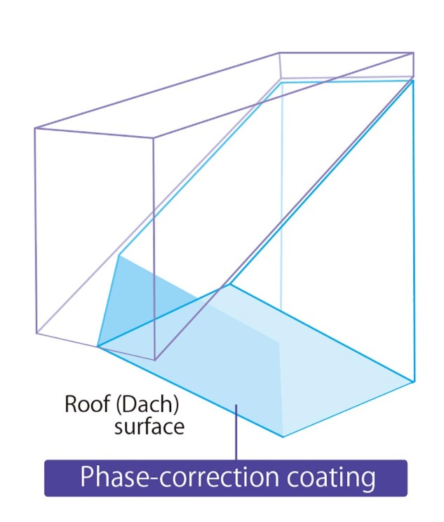
Late 1980s: Roof Prism Phase Issues Engineered Away — Phase-Correction Coatings Turn Roof Prisms from a “Structural Advantage” into a “Performance Advantage”
The main challenge of roof prisms is not “structural complexity,” but an optical fundamental problem: beam splitting and reflections in the roof prism introduce polarization-dependent phase differences, leading to incomplete interference. This manifests as reduced contrast and a “gray” appearance in fine details. Even finely crafted early roof prisms often fell short of high-quality Porro designs in sharpness and micro-contrast.
By the late 1980s, phase-correction coatings began to be applied in high-end roof prism binoculars. Their engineering significance is:
- Compensating phase differences by depositing a specific coating on the roof surfaces;
- Restoring the roof prism’s inherent contrast loss to levels close to Porro prisms;
- Enabling roof prisms to finally achieve both compactness and high optical performance simultaneously.
From this point onward, roof prism binoculars were no longer just “straighter and thinner,” but began a technical trajectory capable of fully replacing traditional Porro designs.
Hidden Trends in Structure and Manufacturing: Engineering Plastics, Magnesium Alloys, and CAD/CAM Enter Binocular Production
During this period, another less visible but industry-defining shift took place:
- Engineering plastics and composites enter the mid-range segment: Materials such as polycarbonate were used for housings and some structural components, reducing weight, improving corrosion resistance, and lowering cost. At the same time, structural ribs and metal frames were needed to maintain stiffness.
- Magnesium alloys adopted in high-end models: These allowed weight reduction without compromising rigidity, especially suitable for sealed bodies and high-strength bridge assemblies.
- CAD/CAM and CNC machining penetrate production: Key components such as prism housings, bridge frames, and focusing helicoids saw greatly improved batch consistency, and collimation/assembly rework became more process-driven.
These trends would accelerate in the 1990s, ultimately driving the industry toward high-end roof prism designs and functional integration.
1990–2000: Roof Prisms Rise, Image Stabilization Debuts, Manufacturing Enters the “Reproducible Era”
The 1990s can be seen as the first major watershed for modern binoculars. From this point on, binoculars were no longer just a combination of “optical design + mechanical craftsmanship”—they began to follow a clear engineering direction. Roof prisms, with phase correction, overcame their inherent shortcomings; image stabilization made handheld high magnification feasible; and CNC machining plus process-driven assembly turned consistency from luck into capability.
The core issue of roof prisms was the phase shift caused when light splits at the prism edges, which degraded contrast and resolution. In 1988, Zeiss first introduced phase-correction (P-coating). By the 1990s, this feature quickly spread from high-end to mid- and high-end roof prism models, giving roof prisms the ability to compete head-to-head with top-quality Porro designs in fine-detail contrast.
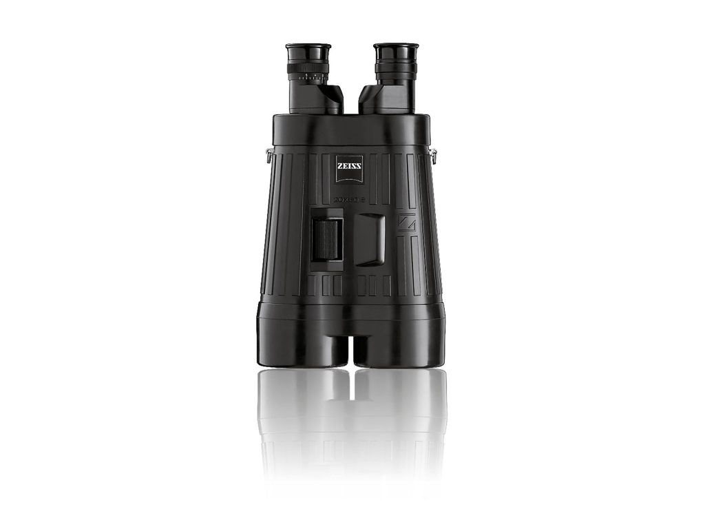
At the same time, image stabilization appeared in “commercial binocular” form for the first time: in 1990, the ZEISS 20×60 S implemented mechanical stabilization, proving that even without batteries, a handheld 20× field could be effectively “held steady.” Canon later combined vari-angle prisms with gyroscopic sensors, bringing stabilization into a more scalable electromechanical path—it wasn’t just “more stable,” it became a platform technology for iterative development. However, over the next 30 years, image stabilization saw little major advancement, and this category of binoculars remained a niche segment due to size and cost constraints.
Another less visible trend in the 1990s was the shift in manufacturing methods. CAD/CAM and more standardized inspection and assembly allowed complex systems—especially roof prism housings and collimation chains—to achieve batch-to-batch consistency. This explains why, starting in the 1990s, the problem of “significant differences between different batches of the same model” gradually diminished—engineering capability controlled it at the foundational level.
The Start of Civilian Binoculars in China: Tracing the Growth Path of FORESEEN OPTICS
The true takeoff of China’s civilian binocular industry in the 1990s was not a matter of “a batch of domestic brands suddenly appearing in a given year.” Rather, it reflected a deeper industrial shift: the production capacity and talent of military optical enterprises began to be oriented toward civilian and export markets. Overseas outdoor demand—especially from Europe and the U.S.—brought with it orders, specifications, and quality systems, setting Chinese optical manufacturing on a long-term OEM/ODM trajectory.
The early path of FORESEEN OPTICS clearly illustrates this history. FORESEEN marks its starting point as 1991: at that time, China’s military optical system began transitioning to civilian production, and Japanese factories were seeking OEM partners in China. FORESEEN entered at this moment, beginning OEM manufacturing for hunting and outdoor optics.
This “first do OEM, then build the system” approach shaped the engineering foundation of 1990s Chinese civilian binoculars: the priority was to run the manufacturing chain smoothly and achieve consistency and delivery capability before focusing on product form and brand language.
In this process, the critical issue was not just “being able to grind lenses,” but turning several hard constraints of binoculars into factory capabilities:
● Two-channel collimation and magnification consistency had to be repeatably deliverable;
● Key components such as prism housings, eyepiece bridges, and focusing helicoids needed to be incorporated into controllable tolerance chains;
● Production management and inspection had to shift from “experience-based judgment” to “batch screening and repair closed loops.”
At the industry level, by the mid-to-late 1990s, Chinese binoculars were already observed by foreign markets to approach the quality of mid- to high-end international products. At the same time, many foreign brands began outsourcing complete or semi-finished production to China—this was not a slogan, but the result of a gradually realized manufacturing system.
FORESEEN’s 1990s factory development reflects this “start from the craft foundation” approach: external sources note that the company received training from Japanese engineers on compact binocular manufacturing and, in 1993, established an optical glass grinding factory, bringing lens processing into its supply chain. The practical significance at the time was clear: as export orders demanded more stable image quality, more consistent edge control, and stricter appearance and assembly standards, the most vulnerable part of the supply chain was often not the design drawings, but lens quality and batch stability. Taking grinding and processing in-house was essentially an engineering solution to offset uncertainty in the 1990s.
Thus, the foundational value of China’s civilian binocular industry in the 1990s can be summarized in three points:
1) Exports and OEM/ODM brought quality systems and specification standards to China, shifting the industry from “can make” to “can consistently deliver”;
2) Factory-based enterprises, exemplified by FORESEEN, transformed lens processing, assembly, inspection, and repair flows into capability assets, providing the groundwork for continued iteration of domestic military and civilian products;
3) These capabilities eventually translated in the 2000s into more tangible product outcomes: widespread adoption of multi-layer coatings, mature sealing and nitrogen purging, fully equipped roof prism systems, and the emergence of domestically developed series and scenario-based product lines beyond OEM logic.
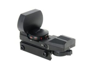
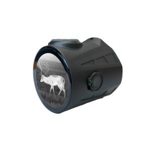
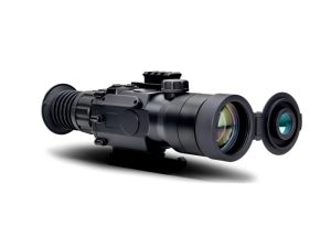
Today, FORESEEN OPTICS has grown into a professional OEM/ODM manufacturing factory serving hundreds of global brand clients, extending its product lines across hunting and outdoor optical instruments. Leveraging China’s current world-leading electronic manufacturing capabilities, FORESEEN OPTICS holds a global innovation position in red dot sights, image stabilization electronics, and miniaturized thermal imaging technologies.
2000–2010: High-End Roof Prisms Fully “Equipped”—Dielectric High-Reflection Coatings, Multifunction Surfaces, Field-Flattener Eyepieces, and an Ergonomic Revolution
Entering the 2000s, competition in high-end binoculars became intensely “engineering-driven.” No single technology could win the game on its own; the real differentiation came from system stacking—prism reflective coatings, phase-correction coatings, anti-reflection coatings, exterior protective coatings, stray light control, field-flattener eyepieces, and ergonomic design all had to be executed properly.
One of the most significant changes of this period was the transition of roof prism reflective surfaces from metallic coatings to dielectric high-reflection coatings. Dielectric stacks pushed reflectivity and stability to a higher level, further improving—or even surpassing—the light transmission and contrast of the roof prism system. In ZEISS’s historical milestones, the 2004 Victory FL is cited as a key reference point (with fluorine/low-dispersion design significantly reducing chromatic aberration), and a series of subsequent surface and system upgrades were documented as a “traceable engineering path.”
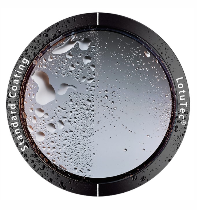
At the same time, exterior surface coatings no longer focused solely on transmission; they were designed to directly address outdoor performance. Hydrophobic, oil- and dirt-resistant, and easy-to-clean protective layers became standard on high-end models. ZEISS’s LotuTec is a typical example, turning “rain beads rolling off, dust resists adhesion” into a tangible user experience—these coatings may seem subtle, but they directly affect continuity of use in the field and maintenance costs.
Eyepiece design also saw key improvements: field-flattener lenses and field curvature correction gradually became common, allowing users for the first time to perceive a consistently clean, sharp image from center to edge on handheld binoculars, rather than relying solely on center sharpness. Nikon’s technical literature explicitly explains that “field-flattener lenses in the eyepiece improve edge clarity”—a clear example of engineering language: acknowledging the presence of field curvature and using controllable optical means to correct it.
2010–2025: Systems Approach Their Limits, Functions Begin to Overflow—High-Transmission Platforms, Ultra-Wide Fields of View, Digital Integration, and Stabilization Becoming Mainstream
From the 2010s onward, the “visible progress” in traditional optical-mechanical systems began to slow—not because there was no room for improvement, but because high-end products had already addressed most of the critical weaknesses. As a result, engineering innovation naturally split into two paths: one continued to extract the maximum from the optical system (higher transmission, stronger micro-contrast, wider fields of view, more stable edge performance), while the other extended functionality outward (modular stabilization, rangefinding/sensors/software ecosystems).
On the “maximizing optical systems” path, ZEISS’s 2012 Victory HT was officially highlighted for achieving a “95%+ transmission” goal, attributed to the synergistic combination of glass, coatings, and prism systems—this was not the victory of any single component, but the result of system-level engineering.
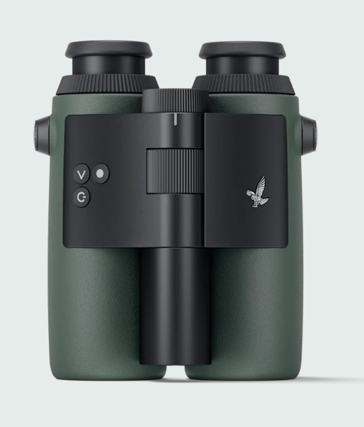
In the “ultra-wide field + ergonomic form” direction, Swarovski’s NL Pure, launched in 2020, effectively redefined the trade-off between field of view and physical size: a larger field was packed into a more compact mechanical frame. The engineering challenge here has never been marketing—it lies in tolerance chains, assembly stability, and long-term reliability. Official press releases emphasized the 2020 launch of the NL Pure and its “revolutionary combination of wide field and compact precision mechanics.”
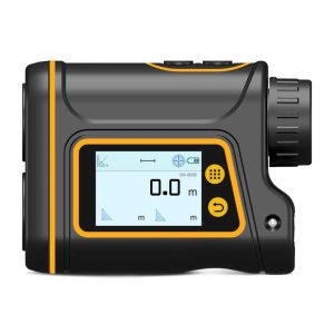
Once optical performance reached a sufficiently high level, functional overflow became inevitable: in 2019, Swarovski’s dG introduced “digital-guided” binoculars, integrating observation, identification, and mobile connectivity into a single workflow. By 2024, AX Visio was even described in the media as a representative “smart binocular” product, showing that this path had evolved from experimental to a clear market trajectory.
Stabilization also clearly “trickled down” during this period: from the benchmark products of the 1990s, it gradually expanded to more magnifications and a broader user base, even giving rise to a new category based on “electronic stabilization / dual-axis gimbals,” indicating that stabilization was evolving into a modular, platform-level capability.
Future Engineering Outlook
Looking ahead, based on years of tracking cutting-edge developments and analysis, binoculars are expected to see new opportunities and transformations in several engineering areas:
High-Precision Aspheric Manufacturing Potential
Aspheric optical elements are highly anticipated for their ability to effectively correct aberrations. Today, high-precision aspheric processing primarily relies on precision glass molding and CNC polishing/turning, achieving sub-micron surface accuracy. While small aspheric lenses are widely used in cameras and microscopes, their application in binocular eyepieces remains a high-end configuration. As processing technologies advance, costs are expected to decrease, making it possible to incorporate an aspheric element into the eyepiece groups of future wide-field binoculars to improve edge image quality or reduce the number of lenses. For example, an aspheric element can correct spherical and coma aberrations while maintaining a wide field of view, ensuring edge sharpness comparable to the center. The maturation of precision techniques such as magnetorheological polishing and ion-beam polishing will ensure consistent batch production of aspheric lenses. As a result, aspheric technology is expected to enable future binoculars to achieve “wide field, low distortion” optical designs, providing superior visual performance without increasing size or weight.
New Rare-Earth Glass Formulations and Chromatic Aberration Correction
The use of rare-earth elements in optical glass remains a forefront of materials research. New glass types containing lanthanum, niobium, yttrium, and other rare-earth elements are emerging, offering high refractive indices while maintaining exceptionally low dispersion (high Abbe numbers). This allows the production of lenses with better chromatic correction than traditional crown/flint combinations. Some newly developed ultra-low-dispersion (ULD) glasses even exhibit partial anomalous dispersion, enabling simplified apochromatic or even triplet-objective designs. Future binocular objectives may adopt these new ED or HD glass types, combined with conventional high-dispersion lenses in innovative assemblies, effectively eliminating axial and magnification-dependent chromatic aberrations across the visible spectrum. Of note are glass availability and environmental safety: previously common radioactive glasses (e.g., thorium-doped high-index glass) have been phased out for safety reasons. Modern rare-earth glasses aim to deliver high performance without harmful components, with manufacturers developing eco-friendly optical glasses that replace lead, arsenic, and other traditional materials. Overall, ongoing advances in rare-earth glass will provide binocular designers with more flexible tools for chromatic correction, enabling crisp, color-free images even at high magnifications—a feat that was unimaginable decades ago.
Coating Technology Evolution and Environmental Adaptability
Optical coating technology still has room for advancement. First, more efficient anti-reflection coatings: today’s top-tier coatings can comprise over 200 layers. Future developments may introduce new material combinations and design algorithms to further reduce average reflectance, potentially achieving <0.1% reflection across the visible spectrum, corresponding to nearly 99.9% transmission and maximizing brightness in low-light conditions. Second, the concept of adaptive coatings may emerge: by integrating smart materials or liquid crystal layers on lens surfaces, coatings could dynamically adjust interference properties according to lighting conditions, optimizing transmission for daytime vs. nighttime or forest vs. marine environments. Third, environmental-resilient coatings will continue to improve. Current high-end binocular front lenses feature superhydrophobic and fingerprint-resistant coatings; future coatings may integrate multiple protective functions—resistance to salt, oil, scratches, and more—into a single layer. Manufacturing advances such as ion-assisted deposition or atomic layer deposition will ensure dense, durable coatings that remain intact and effective over long-term use. Additionally, both military and civilian demand will drive requirements for laser-protective coatings and broad-spectrum coatings covering ultraviolet to infrared, pushing coating technology toward multifunctional applications. Overall, advanced coatings will enable future binoculars to achieve unprecedented performance in light transmission, ghost and flare suppression, and environmental durability, providing users with brighter, clearer, and longer-lasting optical systems.
The Popularization Trend of Modular Image Stabilization
Over the past three years, FORESEEN OPTICS has focused on bringing image stabilization technology from professional applications to the general public, and by 2026 it is expected to be integrated into more traditional binoculars in a modular form. Traditional optical stabilization requires complex built-in mechanisms, whereas modular stabilization refers to designing the stabilization unit as a relatively independent component, making it easier to standardize and mass-produce. Future binoculars may include reserved interfaces for stabilization modules, allowing users to add a gyroscope and movable prism unit for upgraded anti-shake functionality. With the decreasing cost of MEMS gyroscopes and micro-actuators, compact stabilization modules can be embedded into the binocular body without significantly increasing weight. This popularization manifests in affordability, as consumer-grade stabilized binoculars are increasingly common, and ease of use, with stabilization ready to use without complicated calibration. From an engineering perspective, the main challenge is providing stable imaging while maintaining structural reliability, because stabilization mechanisms introduce moving components that may affect cementing and collimation under impact or vibration. Future designs will emphasize structural stability through suspension damping and auto-locking mechanisms, ensuring optical elements return to and remain locked in position when stabilization is off or without power, maintaining basic optical axis alignment. Electronic algorithms, such as digital stabilization, may be introduced as auxiliary tools, for example overlaying indicators, but real-time direct viewing remains the priority. It is foreseeable that the maturation of modular stabilization technology will make “handheld high magnification, tripod-level stability” a common experience, no longer limited to professionals.
Exploring Liquid Lens Technology for Eyepiece Focusing
Deformable liquid lenses are an emerging optical innovation in recent years. They adjust focal length by changing the shape of a liquid interface, without mechanically moving glass elements. Today, commercial liquid lenses are mainly used in compact camera modules for high-speed autofocus. Applying this technology to binocular eyepiece focusing, however, offers unique potential: smooth, continuous focusing with no mechanical wear. In a future concept, a binocular eyepiece could integrate an electrowetting liquid lens, allowing the user to rotate an electronic focus ring that drives liquid deformation and rapidly changes focus over a certain range, avoiding the backlash and wear typical of traditional helical focusing mechanisms. Liquid lenses respond quickly and, in theory, can provide continuous focusing from infinity to close range. They can also automatically compensate for focus shift caused by temperature changes, improving usability across different environments. That said, current liquid lenses face clear challenges in this application, especially aperture size and image quality. Typical liquid lenses are only about 7–10 mm in diameter, which is relatively small for binocular eyepieces, and scaling liquid lenses to larger apertures while maintaining optical quality and stability is technically demanding. However, with advances in materials and packaging—such as multi-droplet arrays to increase effective aperture, or new liquid crystal elastomer lenses—these limitations may gradually be overcome. Major companies have shown interest in this direction; for example, Philips introduced its “FluidFocus” electrowetting zoom concept as early as the 2000s. If liquid lenses achieve a breakthrough in binocular applications, they could deliver a fundamentally new focusing experience: quiet, fast, and precise, with no concern for mechanical wear or sealing failure. In the foreseeable future, liquid lens technology is likely to be intelligently combined with traditional optics, opening a new chapter in binocular engineering design.

The Irreplaceable Value of Binoculars in the Digital Age
Finally, it is worth asking whether traditional binoculars will face “extinction” in an era of smart glasses, high-zoom digital cameras, and rapidly advancing image-stabilization algorithms. From an engineering perspective, binoculars still offer several advantages that are difficult to replace:
● Stereoscopic depth and real presence: Binoculars provide true three-dimensional depth through binocular parallax, something that single-lens cameras or smart glasses cannot fully replicate. Using both eyes creates a strong sense of presence and accurate distance judgment, which is especially valuable in activities like birdwatching and hunting, where estimating range matters. This depth perception comes from the brain’s natural fusion of two images and cannot be naturally reproduced by digital screens, even with 3D display technology.
● Zero-latency, high-definition viewing: A quality binocular effectively brings the human eye closer to distant objects, with no electronic imaging or processing delay. Digital devices, by contrast, always introduce some latency and frame-rate limits between the sensor and the display, which can cause blur or lag in fast-moving scenes. Binoculars deliver a truly real-time optical image, with resolution limited only by the optics and the human eye. In many cases, this exceeds the effective resolution of typical digital displays. For example, a 42 mm binocular can approach the eye’s angular resolution limit, while digital systems remain constrained by sensor pixel density and display resolution, especially for wide fields of view.
● Power-free reliability: Traditional binoculars rely purely on optics and mechanics and require no power source. This makes them highly reliable for long outdoor use, with no concern about batteries running out or electronics failing. Electronic devices, in contrast, are always limited by battery life and may fail at critical moments. As many birdwatchers note, discovering a once-in-a-lifetime species only to find a digital device out of power is deeply frustrating. Binoculars also have very long service lives: if not severely damaged, their optical performance can remain stable for decades. Many experienced users find that a high-quality binocular can last a lifetime, delivering the same image quality even after many years—something rare in fast-cycling digital products.
● Natural color and viewing comfort: Direct optical viewing presents colors and brightness exactly as they exist in nature, without digital processing. While cameras and displays continue to improve, screens still struggle to match the full dynamic range and subtle color perception of the human eye. In high-contrast scenes, binoculars allow the eye to adapt naturally to both highlights and shadows, while digital images may clip or lose detail. Long-term viewing through binoculars is also easier on the eyes, as the observer is looking at the real world rather than a glowing flat screen. Electronic viewfinders and displays can cause eye fatigue over time, whereas optical binoculars are more comfortable for extended observation, such as patrol work or field research.
In summary, although digital technology is rapidly entering the observation field, binoculars remain hard to replace thanks to their stereoscopic vision, real-time imaging, power-free reliability, and natural viewing comfort. Many enthusiasts and professionals continue to rely on traditional binoculars even after trying electronic alternatives. Looking ahead, binoculars are unlikely to disappear; instead, they will coexist and selectively integrate with new technologies, combining pure optical strengths with limited digital functions to enrich the user experience. No matter how technology evolves, binoculars—as a living classic of optical engineering—will retain their practical value and enduring appeal.